19
Alarms
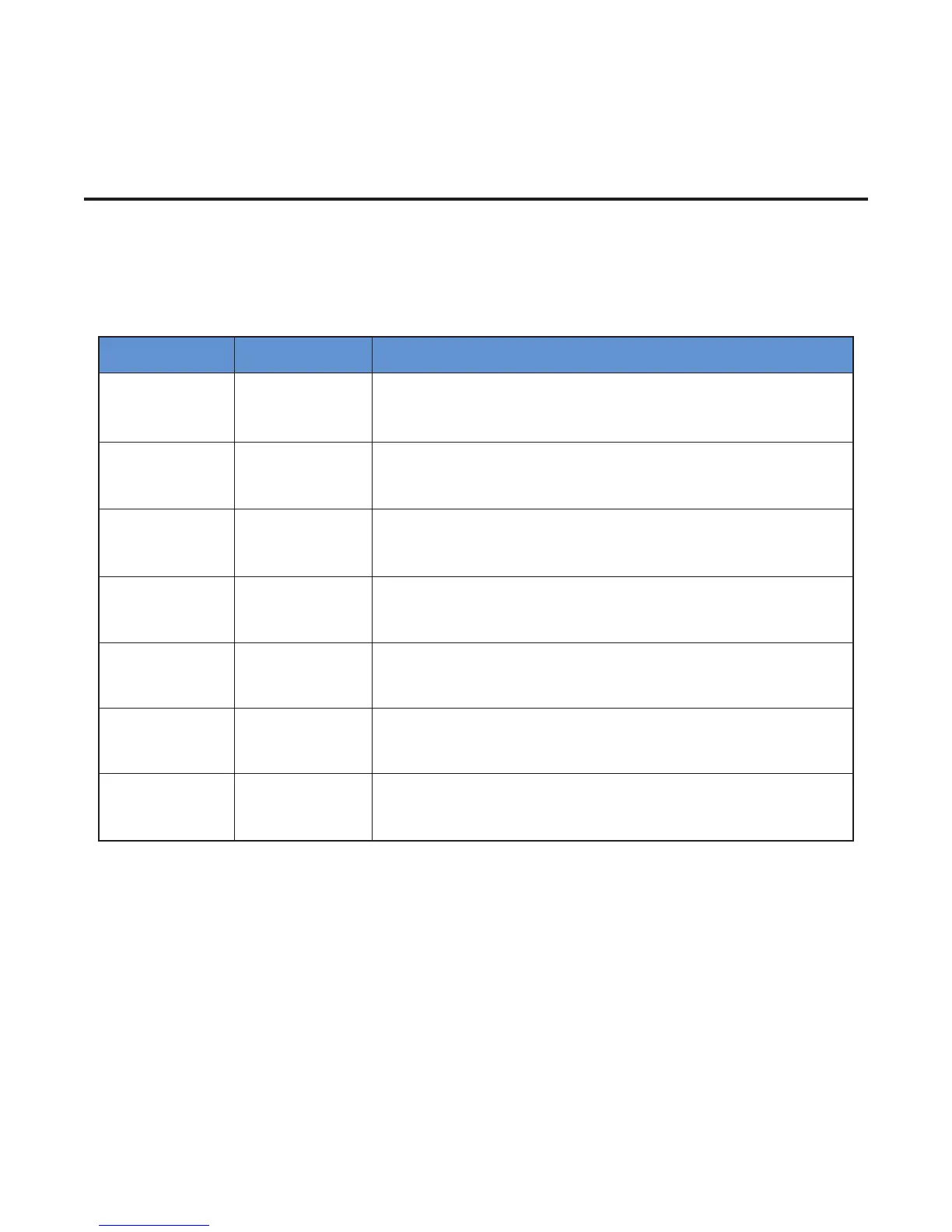
Any alarm condition will be displayed in the bottom
right corner of the Main Screen. Additionally, a red LED
will be illuminated on the front panel under “ALARM”.
The table below illustrates the different types of alarm
where “#” represents circuit number and “X” repre-
sents either sensor A or B
Current Sampling
All active loops are individually tested for 2 seconds
every 2 minutes. During the test, a current load value is
updated on the yellow bar located on the Main Window
and a new GFEP current is automatically and continu-
ously calculated. The Yellow Load LEDs will be illumi-
nated during the sampling test.
Alarm Type Display Solution
Open Sensor SENS #X ERROR
Check if your RTD is correctly connected to the unit or damaged.
Alarm clears automatically. Output will switch to Default Mode. Re-
place RTD if necessary.
Shorted Sensor SENS #X ERROR
Check if your RTD is correctly connected to the unit or damaged.
Alarm clears automatically. Output will switch to Default Mode. Re-
place RTD if necessary.
Low Temperature LO TEMP CKT #!
Sensed temperature is below Lo Temp Alarm Setpoint. Alarm will be
cleared automatically when the sensed temperature is greater than
the Low Temperature Alarm Setpoint, + 5 deg
High Temperature HI TEMP CKT #!
Sensed temperature is above High Temp Alarm Setpoint. Alarm will
be cleared automatically when the sensed temperature is less than
the High Temperature Alarm Setpoint, - 5 deg
High Load HI LOAD CKT #!
Sensed load current is above Hi Current Alarm Setpoint. Alarm will
be cleared automatically when the sensed current < Current Hi Set-
point – 0.5 Amp
Low Load LO LOAD CKT #!
Sensed load current is below Current Lo Setpoint. Alarm will be
cleared automatically when the sensed current > Current Hi Setpoint
+ 0.5 Amp
High GFEP HI GFEP CKT #!
Sensed GFEP current is above the GFEP Hi Setpoint. Alarm will be
cleared automatically when the sensed current < Current Hi Setpoint
- 5 mA
 Loading...

