NOTE: Snap ring ends must be located within one
finger of the input clutch hub. Be sure that snap
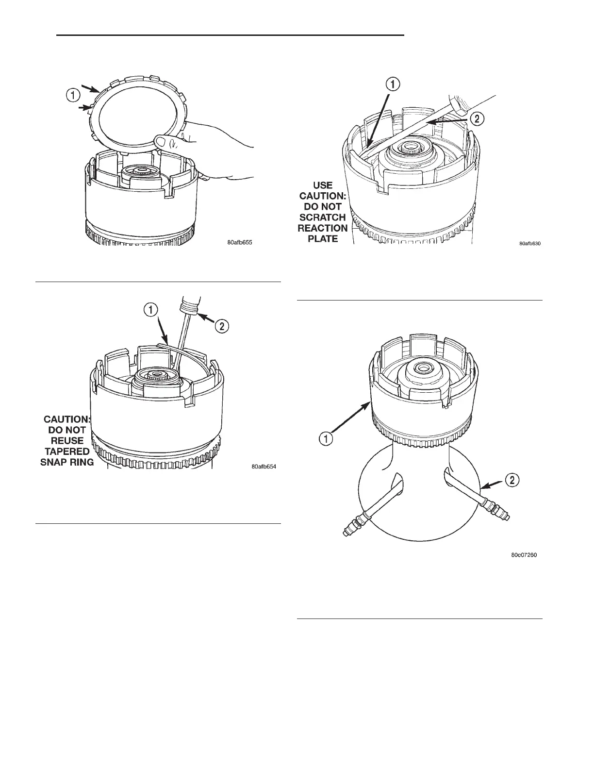
ring is fully seated, by pushing with screwdriver,
into snap ring groove all the way around.
(14) Seat tapered snap ring to ensure proper
installation (Fig. 270).
(15) Install input clutch assembly to the Input
Clutch Pressure Fixture–Tool 8391 (Fig. 271).
(16) Set up dial indicator on the UD clutch pack as
shown in (Fig. 272).
(17) Using moderate pressure, press down and
hold (near indicator) the UD clutch pack with screw-
driver or suitable tool and zero dial indicator (Fig.
273). When releasing pressure on clutch pack, indica-
tor reading should advance 0.005–0.010.
CAUTION: Do not apply more than 30 psi (206 kPa)
to the underdrive clutch pack.
(18) Apply 30 psi (206 kPa) to the underdrive hose
on Tool 8391 and measure UD clutch clearance. Mea-
sure and record UD clutch pack measurement in four
(4) places, 90° apart.
Fig. 268 OD/UD Reaction Plate
1 – OD/UD CLUTCH REACTION PLATE (STEP SIDE DOWN)
Fig. 269 Tapered Snap Ring
1 – OVERDRIVE/UNDERDRIVE CLUTCHES REACTION PLATE
TAPERED SNAP RING
2 – SCREWDRIVER (DO NOT SCRATCH REACTION PLATE)
Fig. 270 Seating Tapered Snap Ring
1 – OVERDRIVE/UNDERDRIVE CLUTCHES REACTION PLATE
TAPERED SNAP RING
2 – SCREWDRIVER
Fig. 271 Input Clutch Assembly on Pressure Fixture
Tool 8391
1 – INPUT CLUTCH ASSEMBLY
2 – INPUT CLUTCH PRESSURE FIXTURE 8391
LH 42LE TRANSAXLE 21 - 95
DISASSEMBLY AND ASSEMBLY (Continued)