DETERMINING No. 4 THRUST PLATE
THICKNESS—INPUT SHAFT END PLAY
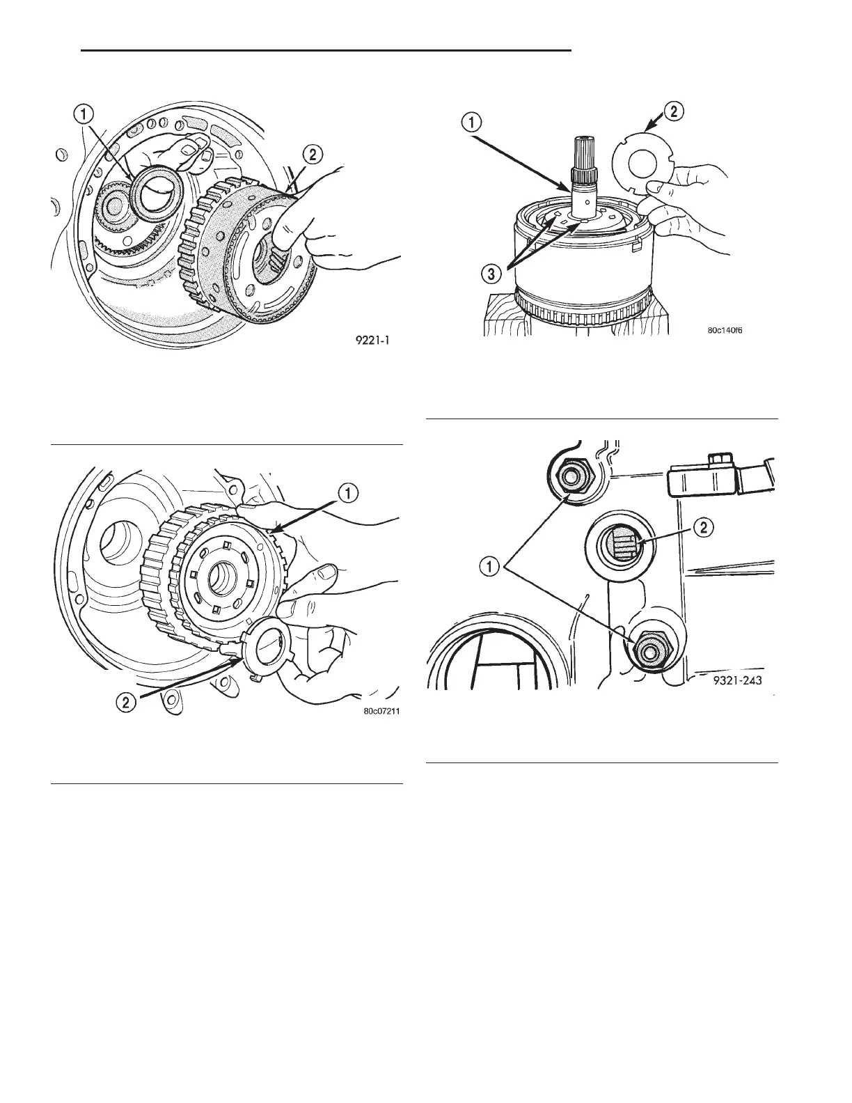
To determine the proper thickness of the No. 4
thrust plate, select the thinnest No. 4 thrust plate.
Using petrolatum (Fig. 340) to hold thrust plate in
position, install input clutch assembly. Be sure the
input clutch assembly is completely seated (Fig. 341).
CAUTION: If view through input speed sensor hole
is not as shown above, the input clutches assembly
is not seated properly.
Remove the oil pump O-ring (Fig. 342). You will be
able to install and remove the oil pump and gasket
very easily to select the proper No. 4 thrust plate.
NOTE: Use screw-in dowels or phillips-head screw-
drivers to align pump to case.
CAUTION: Be sure to reinstall O-ring on oil pump
after selecting the proper No. 4 thrust plate.
Measure the input shaft end play with the tran-
saxle in the vertical position. This will ensure that
the measurement will be accurate.
Fig. 338 Install Front Carrier and Rear Annulus
Assembly
1 – #6 NEEDLE BEARING
2 – FRONT CARRIER AND REAR ANNULUS ASSEMBLY (TWIST
AND PULL OR PUSH TO REMOVE OR INSTALL).
Fig. 339 Install Front Sun Gear Assembly
1 – FRONT SUN GEAR ASSEMBLY
2 – #4 THRUST WASHER (FOUR TABS)
Fig. 340 Select Thinnest No. 4 Thrust Plate
1 – OVERDRIVE SHAFT ASSEMBLY
2 – #4 THRUST PLATE (SELECT)
3 – 3 DABS OF PETROLATUM FOR RETENTION
Fig. 341 View Through Turbine Speed Sensor Hole
1 – TRANSAXLE COOLER LINE
2 – TURBINE SPEED SENSOR HOLE
LH 42LE TRANSAXLE 21 - 113
DISASSEMBLY AND ASSEMBLY (Continued)