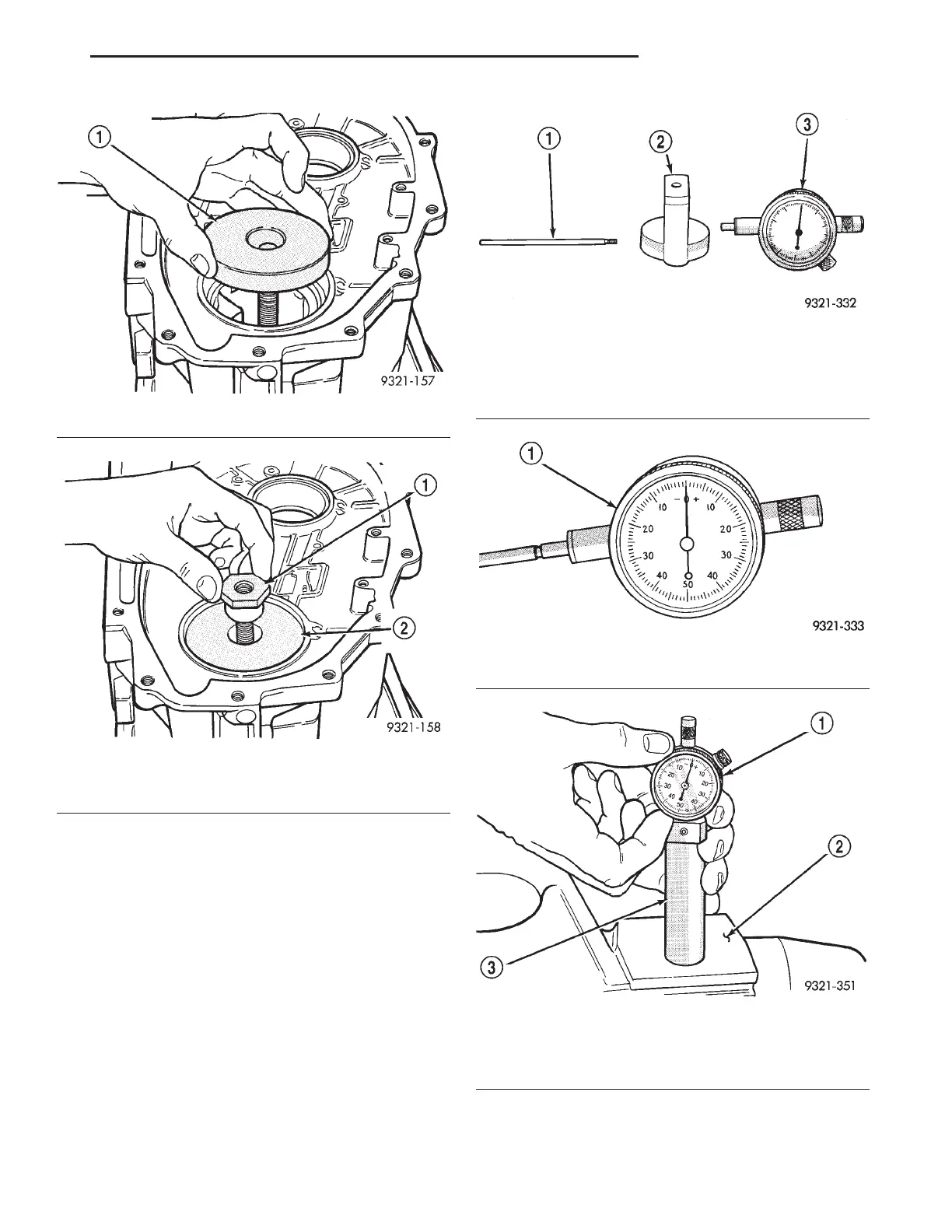
(8) Install dial indicator into locating block Tool
6549-1. Then screw extension rod onto dial indicator.
NOTE: The dial indicator used to make this mea-
surement must have a face that shows 0-50-0 (Spe-
cial Tool C-3339) readings (Fig. 396). All steps from
this point forward will reflect this assumption. This
will give you proper shim thickness.
(9) Before making a pinion depth measurement
the dial indicator must be zeroed. This is done by
placing the dial indicator in the zeroing fixture (spe-
cial tool 6549-6). Then place the zeroing fixture on a
flat surface. Adjust the dial face so the pointer on the
dial indicator lines up with the zero (Fig. 397).
(10) Compress the dial indicator slightly and
insert dial indicator pin into centering block (Fig.
398).
(11) Pivot dial indicator back and forth (Fig. 399)
on centering pin to obtain the shortest distance mea-
surement. This will be the lowest number read-
Fig. 393 Disc Installation
1 – SPECIAL TOOL 6494–2
Fig. 394 Installing Centering Nut
1 – CENTERING NUT
2 – CENTERING DISC
(6494–2)
Fig. 395 Dial indicator, Locating Block and
Extension Rod
1 – EXTENSION ROD SPECIAL TOOL
2 – LOCATING BLOCK SPECIAL TOOL
3 – DIAL INDICATOR
Fig. 396 0-50-0 Dial Indicator
1 – DIAL INDICATOR
Fig. 397 Zero Dial Indicator
1 – DIAL INDICATOR
2 – FLAT SURFACE
3 – ZEROING FIXTURE
LH 42LE TRANSAXLE 21 - 127
DISASSEMBLY AND ASSEMBLY (Continued)