8—FRONT WHEEL SUSPENSION
CHRYSLER SERVICE MANUAL
Remove the mounting bracket from the shock
absorber eye using Tool C-3413. Press mount-
ing bracket and bushing out of eye. The mount-
ing bracket and bushing are serviced as an
assembly only.
To install a new mounting bracket and bush-
ing, refer to Figure 2 and 3, and proceed as
follows:
Position the new mounting bracket so that
mounting holes are at a right angle to shock
absorber. Using Tool C-3413, press mounting
bracket into eye until centered.
CAUTION
Always press against steel sleeve to avoid dam-
age to the assembly, as shown in Figure 3.
b.
Installation
Extend shock absorber piston rod to its full
travel, and slide lower cup washer (concave
side up) over rod and down into position.
Slide shock absorber up through opening in
spring seat into position, (being sure the ex-
tended piston rod enters steel sleeve through
upper bushing).
Install two mounting bracket bolts to lower
control arm and tighten 35 foot-pounds torque.
Install cup washer (concave side down) over
piston rod and down on bushing. Install nut,
tighten to 35 foot-pounds torque, with upper
and lower concave washers bottom against steel
sleeve.
TOOL
[55x1081
Fig.
3—Removing or Installing Mounting Bracket
155x755 ••
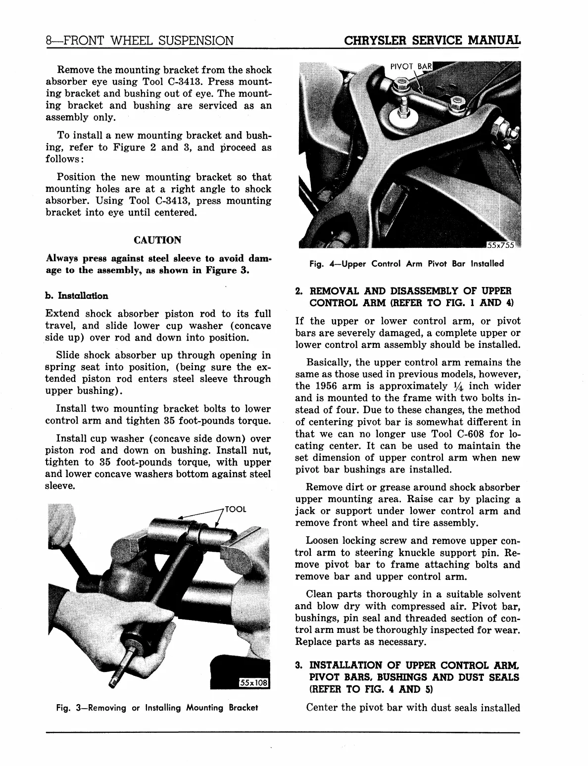
Fig.
4—Upper Control Arm Pivot Bar Installed
2.
REMOVAL AND DISASSEMBLY OF UPPER
CONTROL ARM (REFER TO FIG. 1 AND 4)
If the upper or lower control arm, or pivot
bars are severely damaged, a complete upper or
lower control arm assembly should be installed.
Basically, the upper control arm remains the
same as those used in previous models, however,
the 1956 arm is approximately 14 inch wider
and is mounted to the frame with two bolts in-
stead of four. Due to these changes, the method
of centering pivot bar is somewhat different in
that we can no longer use Tool C-608 for lo-
cating center. It can be used to maintain the
set dimension of upper control arm when new
pivot bar bushings are installed.
Remove dirt or grease around shock absorber
upper mounting area. Raise car by placing a
jack or support under lower control arm and
remove front wheel and tire assembly.
Loosen locking screw and remove upper con-
trol arm to steering knuckle support pin. Re-
move pivot bar to frame attaching bolts and
remove bar and upper control arm.
Clean parts thoroughly in a suitable solvent
and blow dry with compressed air. Pivot bar,
bushings, pin seal and threaded section of con-
trol arm must be thoroughly inspected for wear.
Replace parts as necessary.
3.
INSTALLATION OF UPPER CONTROL ARM,
PIVOT BARS, BUSHINGS AND DUST SEALS
(REFER TO FIG. 4 AND 5)
Center the pivot bar with dust seals installed
MyMopar.com
 Loading...


