CIAS Elettronica S.r.l. Ed. 2.2
Installation Handbook page 31 to 43 ERMO 482
3. CONNECTIONS
3.1 Terminal Blocks, Connectors and Circuits Functions
3.1.1 Transmitter Circuit
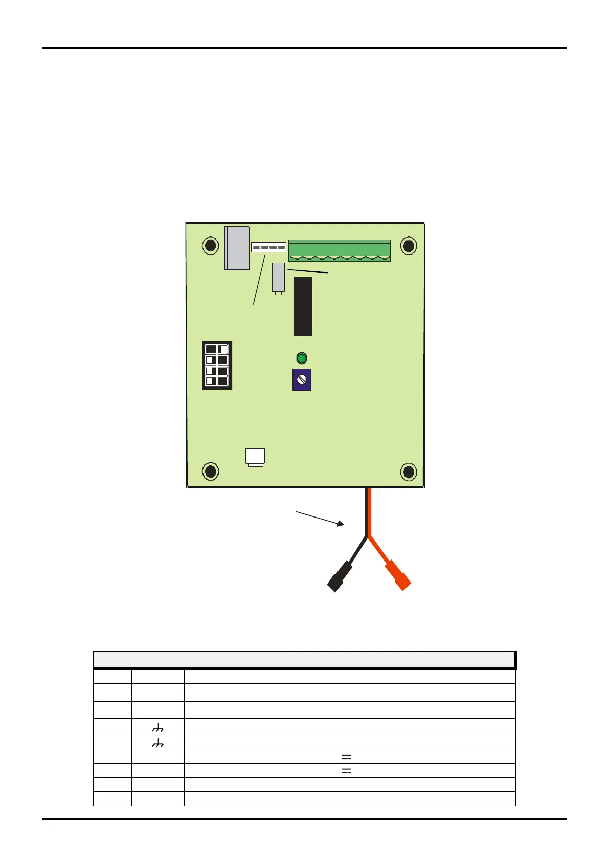
The following figure and tables show the terminal block and connector function present on the
ERMO 482 TX board.
8
3
6 1
4
5
2
7
Tamper
Fuse
Main Led
ON
OFF
Channel
Selector
1
2
3
4
TX
4
3 2
1
Red faston to battery positive
Test
Connector
Bulb
DS1
MS1
F1
MW Connector
Figure 8 Layout of connectors, jumpers, LEDs and presetting in transmitter board
TRASMITTER MS1 TERMINAL BLOCK
Mains Ac Power Supply input (19 V~)
Mains Ac Power Supply input (19 V~)
Dc Power Supply input (13,8 V )
Dc Power Supply input (13,8 V )
Tamper relay contact (Normally Closed) + Bulb contact
Tamper relay contact ( Closed) + Bulb contact