CIAS Elettronica S.r.l. Ed. 2.2
Installation Handbook page 41 to 43 ERMO 482
Note: too low integration can cause unwanted alarms.
We suggest to adjust the min. integration at no less than 30 % (trimmer position). Too
much integration can miss alarm in case of running intruder. We suggest to adjust the
max. integration at no more than 80 % (trimmer position). Higher integration value can be
adopted when the barrier can't be crossed by running intruder, ( the barrier installation is
along a building wall).
o) Press key “buzzer” (15) untill the buzzer enabling led “buzzer On” (16) is on.
When there are no movements in the protection field check that the buzzer is mute. If
otherwise, press key “ buzzer adj.” (14) till it turns off. If when activating the function
the buzzer is already mute press key “ buzzer adj.” (13) till an intermittent operation
is obtained, afterwards slightly press key “ buzzer adj.” (14) till it switches off.
p) Carry out the crossing trials to check for the presence of an intermittent sound and then,
following the presence of an alarm, for a continuous buzzer and Alarm led is off.
Receiver unit (alarm for intrusion detection).
q) Check that the buzzer is not active for no moving object into the protected field. If the
buzzer ring (also in an intermittent manner) the protection field is in some way disturbed.
r) If the protection field is crossed by a very big object, the Channel led turns off, this
means an interruption of RF signal.
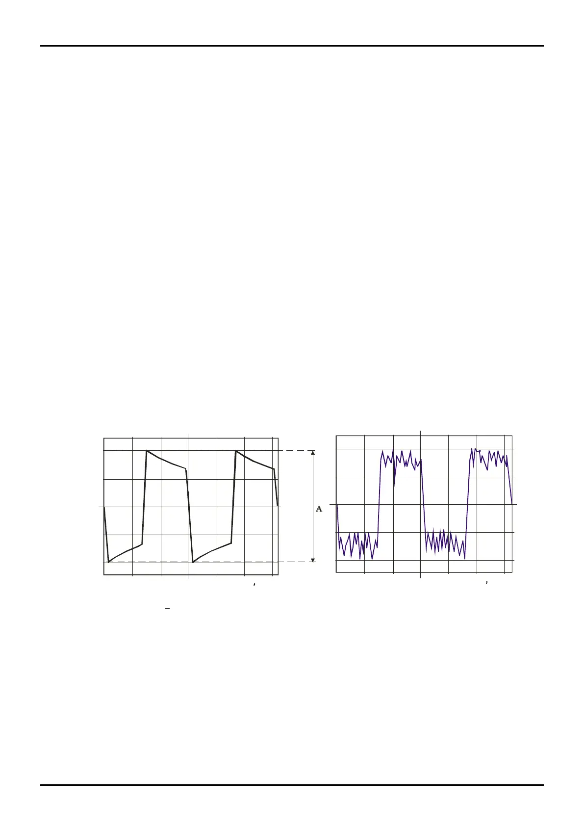
s) The STC 95 is provided with an RCA (23) connector which, through the cable supplied,
allows to check the wave form of the received signal. An oscilloscope (any of the types
present on the market) is utilised for this check. A good connection between the
transmitting head and the receiving head produces the waveform illustrated in fig. 13.
100 us/div.
50 mV/div.
50 mV/div.
100 us/div.
A = 200 mVpp (+ 10%)
Figure 14 - not correct waveform (excessive noise)
Figure 13 - Correct waveform
A bad installation produces the waveform illustrated in fig. 14.
Note the noise at the tip of the square wave. This means that the signal is not good.
Therefore, repeat the pointing operations till the waveform shown in fig. 13 is obtained.
In case of bad barrier installation the waveform will be like the one in fig. 14.
All the data concerning the tests made on the plant must be reported on the test sheets
supplied for each barrier. This will make the servicing operations easier to carry out.
t) Place the front cover cap back again and regularly fasten it with the screws provided in
order to obtain good water proofing.