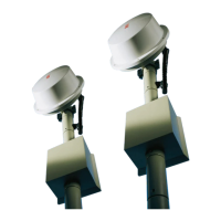
CIAS Elettronica S.r.l. Ed. 2.2
Installation Handbook page 42 to 43 ERMO 482
5. MAINTENANCE AND ASSISTANCE
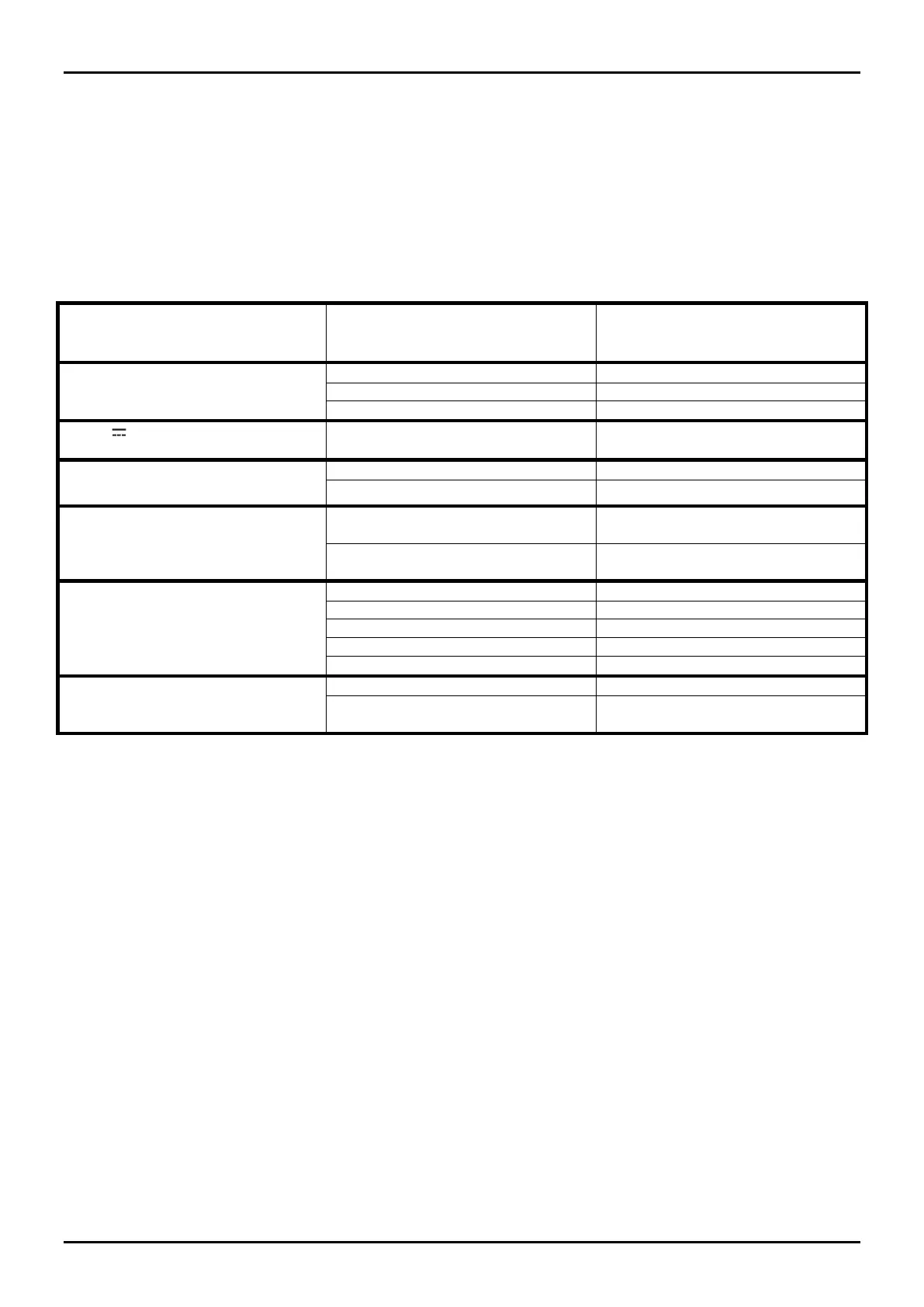
5.1 Troubleshooting
In case of false alarm, check the parameters recorded during the Installation phase (on
attached Test Sheet), if there are divergences with permitted limits check again the related
points in chapter "Adjustment and Testing (4)"
Power Supply Led Off
( Tx and / or Rx )
13,8 V o 19 V~ not correct and /
or not sufficient ( see par. 3.2.1)
Length and / or cable section
not proper
Modify connection and / or cable
Set the same channel on Tx / Rx
Movement or obstacle in the
protected field
Ensure that nothing is in the field
Remake the alignment ( see par
4.1.1 or 4.1.2 )
Antiremoval bulb in wrong
position ( not vertical )
Check position of antiremoval
bulb
5.2 Maintenance kits
The Maintenance Kits are composed by circuits equipped with microwave cavities, their
substitution is very easy: The Maintenance Kits is always presetted for the maximum
performance i.e. 200 m. The max. performance Kit avoids the needs of four types of Kits for
the four types of barrier. By this way the maintenance people can simply operate on
installations maintenance without purchase the entire barrier.
Unlock the only one fixing screw and install the new circuit into related plastic guides present
on the bottom box.
The circuit and cavity substitution on boot transmitter and receiver heads doesn’t
changes the heads alignment, and so no new alignment is required