EasyManua.ls Logo

cias MANTA - User Manual

cias MANTA
64 pages
Go to English
Print Icon
To Next Page IconTo Next Page
Loading...
20MACIE0455
MANTA
Barriera a Microonde
per protezioni esterne
Manuale di Installazione
External Microwave Protection
Barrier
Installation Handbook
Edizione / Edition 1.5
Question and Answer IconNeed help?

Do you have a question about the cias MANTA and is the answer not in the manual?

Overview

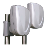
MANTA is a digital microwave barrier from CIAS designed for both internal and external volumetric protection. This system detects the presence of moving bodies within a sensitive field established between a Transmitter (TX) and a Receiver (RX). The received signal is digitally analyzed using Fuzzy logic methods, which allows for excellent detection performance and a reduction in false alarms.

Technical Specifications:

The MANTA barrier is available in two range options:

  • MANTA / 50: 50-meter range
  • MANTA / 80: 80-meter range

Frequency:

  • F1: 10.5 GHz (Min), 10.6 GHz (Max), 500 mW e.i.r.p.
  • F2: 9.5 GHz (Min), 9.975 GHz (Max), 25 mW e.i.r.p.
  • F3: 9.2 GHz (Min), 9.5 GHz (Max), 25 mW e.i.r.p.
  • F4: 10.5 GHz (Min), 10.525 GHz (Nom), 10.6 GHz (Max), 500 mW e.i.r.p.

Modulation: Pulsed, with a 50/50 duty cycle. Number of channels: 16

Power Supply:

  • Nominal: 13.8 Vdc
  • Operating range: 11.5 V to 16 V

Current Consumption (at 13.8 Vdc):

  • TX in surveillance: 80 mA
  • TX in alarm: 50 mA
  • RX in surveillance: 58 mA
  • RX in alarm: 55 mA

Relay Contacts (100mA C-NC):

  • Intrusion alarm (RX)
  • Radome removal (TX+RX)
  • Fault (TX+RX)

LEDs:

  • Intrusion alarm (RX) Red LED: OFF (Not active)
  • Radome removal (TX+RX) Red LED: OFF (Not active)
  • Fault alarm (TX+RX) Red LED: OFF (Not active)

Physical Characteristics:

  • Weight without battery (TX): 800 g
  • Weight without battery (RX): 800 g
  • Diameter: 205x160 mm
  • Depth (brackets included): 200 mm
  • Working temperature: -35 °C to +65 °C
  • Performance level: 3°
  • Box protection level: IP55

Usage Features:

Installation:

The MANTA barrier offers flexible installation options. It can be mounted on a pole or wall. For pole installation, the recommended height from the ground to the center of the antenna is 900 mm (ranging from 850 to 950 mm). The pole should be buried in concrete with radial anti-rotation elements. For wall mounting, the length of the bracket depends on the wall type and the distance between TX and RX. The facade/wall becomes the working plane for the barrier, and it is crucial that there is only one working plane. Considerations for wall installation include using the correct bracket, choosing the appropriate height, positioning the barrier to account for its shadow zone and lobe of protection, verifying the flatness of the wall, and checking for vegetation along the path.

Ground Conditions and Obstacles:

It is not recommended to install the device along paths with high grass (over 10 cm), ponds, longitudinal waterways, or rapidly changing terrain. Metallic fences can cause microwave reflections; therefore, they should be securely fixed, not installed parallel to the path, and if two metallic fences delimit the sensitive beam, the corridor between them should be at least 5 m wide. Trees, hedges, and general vegetation near or within the protection beams require careful attention as they can grow and move with the wind, potentially causing false alarms or creating dead zones.

Beam and Dead Zone Calculation:

CIAS provides a free application called "CIAS Volumeter" (available on their website, App Store, and Google Play) to theoretically calculate the microwave beam dimensions and dead zones based on TX-RX distance and sensitivity.

Microwave Working Plane:

The working plane is the surface that reflects the microwave beam, enabling the barrier's operation. The distance between the antenna's center and the working plane is the "barrier height," which depends on the ground surface type (asphalt, concrete, grass, etc.). The working plane must be singular. Walls or metallic fences nearby can cause the microwave to "see" two planes (wall/fence and ground). The correct height is determined using the built-in alignment tools to ensure microwave field stability.

Alignment and Verification:

MANTA barriers feature an electronic alignment system, parameter adjustment, and test system, simplifying installation and maintenance without special tools.

Transmitter Operations:

  1. Remove Radome: Unscrew three screws and gently remove the front cover, which opens the "Tamper" microswitch.
  2. Power Connection: Connect 13.8 Vdc power to terminals 1 and 2 of MS2.
  3. Set Track Number:
    • Local Assignment (not remote modifiable): Set a number from 1 to 99 using SW2 (tens) and SW3 (units) commutators (00 for track 100). If set to 00 at first power-on, press S1 after setting a different number.
    • Local Assignment (remote modifiable): Set SW2 and SW3 to 0, press S1, then set the desired number (1-99). Close the "Tamper" microswitch; D6 (Fault) and D5 (Tamper) LEDs will light for 3 seconds, confirming acquisition, then turn off for 3 seconds, returning to normal operation.
  4. Set Channel: Rotate hexadecimal switch SW1 to a position between 0 and F to select one of 16 modulation channels. Using different channels for different barriers enhances anti-sabotage capabilities. Setting to F prevents channel alarm events.

Receiver Set-up:

  1. Remove Radome: Similar to the transmitter, remove the front cover to open the "Tamper" microswitch.
  2. Power Check: Verify 13.8 Vdc at terminals 1 and 2 on MS2.
  3. Activate Tamper Switch: Ensure S2 is activated (open circuit).
  4. Barrier Alignment: Select position 1 on SW1. Push S3 to acquire the signal level and freeze AGC. The buzzer will emit a pulsed sound, indicating proper working level.
  5. Horizontal Alignment: Gently unscrew bracket screws and move the receiver horizontally to find the maximum received signal. The buzzer's pulse frequency indicates signal level changes. Push S3 again when the buzzer frequency decreases (proper working level) and move the head horizontally in the same direction.
  6. Vertical Alignment: Similar to horizontal alignment, adjust vertically to maximize the received signal.
  7. Pre-alarm Thresholds (SW1 Position 3): Read/write pre-alarm thresholds. Lower values increase sensitivity.
  8. Alarm Thresholds (SW1 Position 4): Read/write alarm thresholds. Walk-Test mode is activated here, where the buzzer indicates signal perturbations.
  9. Masking Thresholds (SW1 Position 5): Read/write upper and lower masking thresholds, which detect field variations due to snow accumulation or deliberate attempts to bypass.
  10. Upper Pre-alarm Threshold (FSTD) (SW1 Position 6): Read/write upper pre-alarm threshold for Fuzzy Side Target Discrimination (FSTD) system, which reduces sensitivity to lateral disturbances.
  11. Upper Alarm Threshold (FSTD) (SW1 Position 7): Read/write upper alarm threshold for FSTD.
  12. Barrier Number (SW1 Position 8): Select a unique barrier number (1-99, 00 for 100) for RS485 communication.
  13. Monitor Thresholds (SW1 Position 9): Read/write monitor thresholds, which define when signal recording begins.
  14. Working Phase (SW1 Position 0): Push S3 to store all selected parameters.

Synchronization:

For synchronized operation of two transmitters, connect terminals 8 "SYNC" and 7 "GND" on both TX units. One TX is set as "Master" (Jp3 "OUT") and the other as "Slave" (Jp3 "IN"). Synchronization wires should be as short as possible (max 10 meters); for longer distances, use a SYNC 01 repetition circuit.

Stand-by Function:

Connect terminal 7 "ST.BY" on the receiver to ground and terminal 5 "ST.BY" on the transmitter to ground. Stand-by deactivates event recording in historical and monitor files but does not inhibit barrier operation.

Test Function:

Connect terminal 6 "TEST" on the transmitter to ground to activate the test. If successful, alarm relays on the receiver will activate after 10 seconds. Periodic tests are recommended for high-risk protection.

Serial Line RS-485:

Both TX and RX units have a standard RS-485 serial interface for communication. Parameters: Asynchronous Half-Duplex, 9600 b/s, 8-bit character, no parity, 1 stop bit. Connections are "multi-drop" (BUS) type. Use a low-capacity, twisted, shielded cable (< 70 pF/m), e.g., Belden 9842. The maximum bus length is 1200 m. For longer distances or star architectures, use BUS-REP repeaters/regenerators. Up to 32 devices (TX/RX) can be connected per line. The shield must be grounded at only one point, near the power supply.

Software Management:

A PC with "WAVE-TEST2 CIAS" software can be used to view and manage all barrier software parameters, including analog levels of thresholds and received signals.

Maintenance Features:

Troubleshooting:

The manual provides a table of common defects, possible causes, and solutions.

  • Fault LED ON: Check power supply, barrier temperature, TX oscillator, or TX/RX failure.
  • Alarm LED ON: Check for movement/obstacles, re-do alignment, or re-do channel acknowledgment.
  • High AGC Voltage: Re-do alignment or remove obstacles.
  • Tamper LED ON: Check microswitch position or tilt bulb position.
  • Fault LED ON (TX only): Change TX circuit or MW part.

Maintenance Kits:

CIAS offers maintenance kits with circuit boards fitted with microwave cavities. Replacing these boards does not require re-alignment of the heads.

cias MANTA Specifications

General IconGeneral
Brandcias
ModelMANTA
CategoryProtection Device
LanguageEnglish

Related product manuals