© CIAS Elettronica S.r.l. Ed. 1.0
Installation Handbook page 35 of 59 MANTA 50 – 80
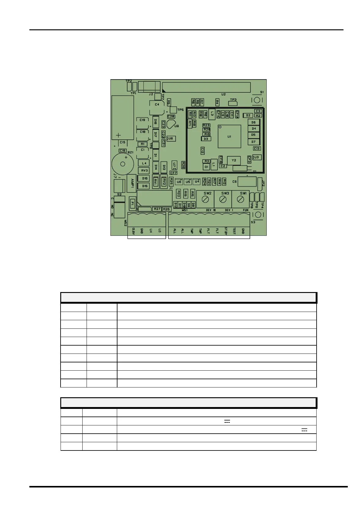
3.1.2 Receiver Circuit
Figure 9 Layout of connectors, jumpers, LED and presetting in receiver board
The following tables shows the connector pin functions present on MANTA Receiver board.
RECEIVER TERMINAL BLOCK MS1
Term Symbol Function
1
ALL 1 Alarm relay contact (Normally Closed)
2
ALL 2 Alarm relay contact (Normally Closed)
3
TMP Tamper relay contact (Normally Closed) + bulb contact
4
TMP Tamper relay contact (Normally Closed) + bulb contact
5
FLT Fault relay contact (Normally Closed)
6
FLT Fault relay contact (Normally Closed)
7
ST BY Auxiliary input for Stand-By command (Norm. Open from GND)
8
TEST Auxiliary input for Test command (Norm. Open from GND)
9
GND Ground auxiliary connection
RECEIVER TERMINAL BLOCK MS2
Term Symbol Function
1
+13,8 Positive Dc Power Supply (+13,8 V
)
2
GND 1 Negative Power Supply and Ground connection for Data (0 V
)
3
LH + RS 485 (High Data Line)
4
LO - RS 485 (Low Data Line)