© CIAS Elettronica S.r.l. Ed. 1.0
Installation Handbook page 36 of 59 MANTA 50 – 80
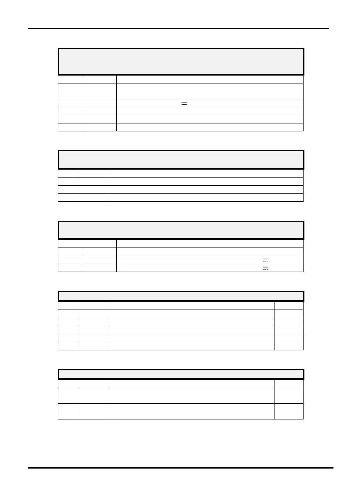
RECEIVER CONNECTOR J1
10 pin Connector for local PC Serial Line connection (Mwatest or
WAVE-TEST SW )
Term Symbol Function
1-2-4-
6-8-10
N.C.
Not Connected
3
+13,8 Power Supply (13,8 V
) Converter interface RS-485/232
5
LO Low Line for RS 485
7
LH High Line for RS 485
9
GND Ground
RECEIVER CONNECTOR J2
Connector for MW detector
Term Symbol Function
1
GND Ground connection for MW detector
2
DET Connection for MW detector
3
GND Ground connection for MW detector
RECEIVER CONNECTOR J7
Connector for External Buzzer
Term Symbol Function
1
COM Command for external buzzer
2
+13,8 Power Supply voltage for external buzzer (+13,8 V
)
3
+13,8 Power Supply voltage for external buzzer (+13,8 V
)
RECEIVER LEDS
N° Symbol Function Default
1
D12 Alarm indication
OFF
2
D11 Tamper indication
OFF
3
D10 Fault indication
OFF
4
D9 Alignment and setting functions
OFF
5
D8 Alignment and setting functions
OFF
RECEIVER JUMPERS
N° Symbol Function Default
1
Jp1 RS485 Line termination (Jp1 position 1/2 = line NOT
terminated)
1/2
Closed
2
Jp2 Enable for FW download (Jp2 position 2/3 = FW
download NOT enabled)
2/3
Closed