© CIAS Elettronica S.r.l. Ed 1.1
Installation Manual Page 34 of 51 Sioux Pro 2
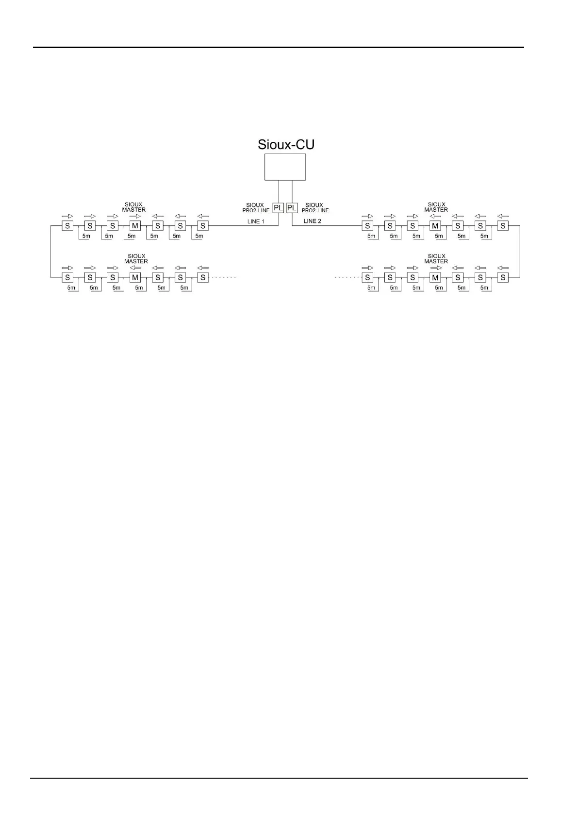
2.3 SiouxPro2-Line
SiouxPro2-Line is a voltage step up (DC / DC converter from 13,8 to 27,6 Vdc) to be used
only with the SIOUX PRO 2 1500m system and its sensors.
It must be installed between the Sioux-CU-Pro2 and the first sensor as shown below.
It is possible to choose whether to connect the first sensor in the field with the terminal
block (CON3) or with the RJ45 port (CON4). Refer to the specific installation manual.
2.4 SiouxPro2-LFI Line insulators (optional)
SiouxPro2-LFI can detect short circuits both on the power supply and on the serial data line and
when a short is detected, they interrupt/isolate the line safeguarding the functionality of all the
downstream sensors.
It is placed between the Sioux Pro 2 sensor kits and is identified with a violet sticker.
They come with their own protective box and two 2,5 meters cables.
It is possible to install a maximum of 19 SiouxPro2-LFI for each line (refer to the specific
installation manual).
2.5 SiouxPro2-Redund (optional)
SiouxPro2-Redund is a module to be installed at the end of each branch to obtain redundancy
(refer to the specific installation manual).
2.6 Installation of the Sioux-CU-Pro2
The Sioux-CU-Pro2 control unit is mounted in a cabinet which also houses the battery and power
supply (available code SIOUXPRO2-CU). To this unit will be connected the left and right sensor
branches, the power, the tamper cabinet, ethernet cable for PC connection or RS485 serial cable
for connection to Quasar control panel or to an IB-System-Rack.
2.7 System configuration
Use the “Sioux-Test-Pro” software to configure the system.
Each system can be divided into a maximum of 80 zones and at each zone can be assigned the
required characteristics (intrusion alarm threshold, cut alarm threshold, etc.).
It is possible to assign the characteristics not only by zone, but also by individual sensor. For
more detailed description, see the Sioux-Test-Pro manual.