© CIAS Elettronica S.r.l. Ed 1.6
Installation Manual Page 34 of 43 Sioux
3.3 Sioux-Master
The Sioux-Master board communicates with the Sioux-CU using an RS485 serial channel.
It responds to polling from the Sioux-CU and transmits the electrical signal produced by the
sensor on board as well as the electrical signals produced by the sensors on board the
associated Sioux-Slaves.
For each serial connection on the Sioux-CU it is possible to connect up to 10 Sioux-Master, each
with an address different from the others.
The addresses assigned to the Sioux-Masters depends on the order in which they are connected
along the serial line and can have the values of 4, 11,18, 25, 32, 39, 46, 53, 60, and 67.
Sioux-Master board acquires the signals from the internal sensor plus those from the other six
boards (Sioux-Slave boards), converts them in digital format, assigns to each one a proper
address and then transmits these signals by an RS485 line to the Control Unit (CU).
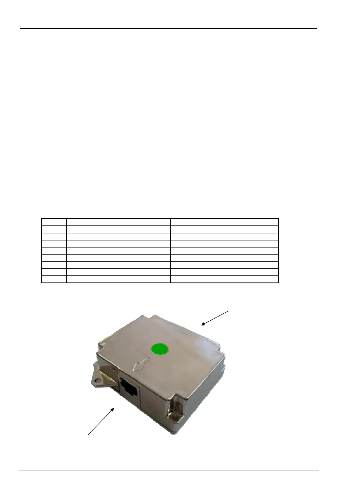
Below is a description of the two connectors on the board:
Pin Connector 1 Functions Connector 2 Functions
1 Signal from slave 3 Signal from slave 4
2 Signal from slave 2 Signal from slave 5
3 Signal from slave 1 Signal from slave 6
4 GND GND
5 Power Supply 13,8 Vcc Power Supply 13,8 Vcc
6 Power Supply 13,8 Vcc Power Supply 13,8 Vcc
7 RS485-Low Line LO RS485-Low Line LO
8 RS485-High Line LH RS485-High Line LH
CONNECTOR 2
CONNECTOR 1