EN - 15 NA 06.130 C
Faults Probable causes Instructions
Suction pressure too low
Heat load below unit capacity
Air or water energy transfer fluid flow rate on the user
side too low
Adjust the air or water flow rate to the specified value
Lack of refrigerant Look for leaks and top up the charge, taking care to use
the type of refrigerant specified on the name plate.
Poor refrigerant supply Check the expansion valve
Make sure the dehumidifier filter is not fouled
Excessive discharge pressure
Fan problem Check the direction of rotation of the fans
Condenser fouled Clean the coil to improve its performance
Air too hot Switch to high speed
Make sure air is not being recirculated between several
units placed side by side.
Refrigerant overcharge Check and adjust the charge
Insufficient oil Oil not topped up after servicing Top up with oil
Motor winding fault
Start-ups too close together; short-cycle protection
not working properly
Set the correct time between two start-ups
Overload protection disrupted or defective Adjust or replace the overload protection
Insufficient power supply voltage Check the electrical wiring; if necessary, contact your
electricity supplier
Discharge temperature insufficient and
close to condensation temperature Compressor draws in too much liquid
Check and adjust the refrigerant charge
Check the expansion valve
Moisture indicator sight glasses
The sight glass remains yellow
Excessive moisture in the circuit
Refer to the section entitled
"Refrigerant connection"
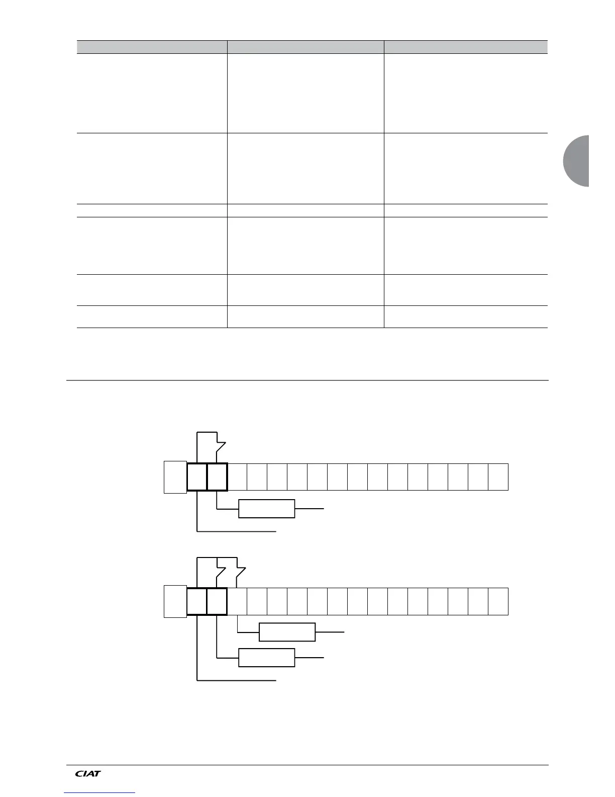
24 - CUSTOMER CONNECTION OF REMOTE CONTROL FUNCTIONS
24.1 General fault alarm
1
3
4
5
6
7
8
9
10
11
12
13
14
15