EasyManua.ls Logo

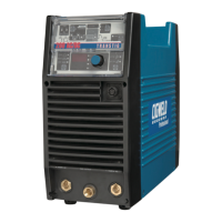
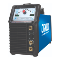
CIGWELD TRANSTIG 200 User Manual

CIGWELD TRANSTIG 200
128 pages
To Next Page IconTo Next Page
Page #1 background imageLoading...
Page #1 background image
200
Amp
240
V
1
50
60
Hz
INVERTER
TRANSTIG
®
INVERTER ARC WELDER
200 AC/DC
Service Manual
Revision No: AB Issue Date: January 10, 2014 Manual No.: 0-5001
Operating Features:

Table of Contents

Questions and Answers:

CIGWELD TRANSTIG 200 Specifications

General IconGeneral
BrandCIGWELD
ModelTRANSTIG 200
CategoryWelding System
LanguageEnglish

Summary

SECTION 1: ARC WELDING SAFETY INSTRUCTIONS AND WARNINGS

1.01 Arc Welding Hazards

Details potential hazards and protective measures during arc welding operations.

1.02 PRINCIPAL SAFETY STANDARDS

Lists key safety standards and regulations applicable to welding operations.

1.03 DECLARATION OF CONFORMITY

Statement confirming compliance with relevant European directives and national legislation.

SECTION 2: INTRODUCTION

2.01 How To Use This Manual

Guidance on interpreting manual symbols, warnings, cautions, and notes.

2.02 Equipment Identification

Information on locating and recording unit identification numbers for future reference.

2.03 Receipt Of Equipment

Instructions for checking equipment completeness and inspecting for shipping damage.

2.04 Symbol Chart

A reference chart for symbols found on the welding equipment and in the manual.

2.05 Description

Overview of the Transtig 200 AC/DC's features, processes, and enclosure.

2.06 Functional Block Diagrams

Illustrates the internal functional relationships of the power supply components.

2.07 Transporting Methods

Safe procedures for lifting, moving, and transporting the welding power source.

2.08 Parameter Specifications

Detailed technical specifications and performance ratings for the welding power source.

SECTION 3: INSTALLATION

3.01 Environment

Guidelines for suitable operating environments and conditions for the welding equipment.

3.02 Location

Recommendations for placing the welder to ensure proper ventilation and operation.

3.03 Electrical Input Connections

Critical safety warnings and procedures for connecting the welding power source to electrical input.

3.04 Mains Supply Voltage Requirements

Specifies required mains voltage, frequency, and circuit recommendations for operation.

3.05 High Frequency Introduction

Importance of correct HF installation and warnings regarding explosives and computers.

3.06 High Frequency Interference

Explains how HF interference can occur and methods to minimize it.

3.07 Duty Cycle

Definition of duty cycle and consequences of exceeding rated limits.

SECTION 4: OPERATOR CONTROLS

4.01 Transtig 200 AC/DC Controls

Identifies and describes the function of front panel controls and sockets.

4.02 Weld Process Selection for Transtig 200 AC/DC

Table showing weld process and mode selections for different welding applications.

4.03 Weld Parameter Descriptions for Transtig 200 AC/DC

Explains the function of various weld parameters like Pre-Flow, Hot Start, etc.

4.04 Weld Parameters for Transtig 200 AC/DC

Provides tables with parameter ranges, factory settings, and incremental units for different weld modes.

4.05 Power Source Features

Highlights key features of the power source, including digital control and self-diagnosis.

SECTION 6: SEQUENCE OF OPERATION

6.01 Stick Welding

Step-by-step guide for setting up and performing stick welding operations.

6.02 AC or DC HF TIG Welding

Procedures for setting up and performing AC/DC HF TIG welding.

6.03 Slope Mode Sequence

Diagram and explanation of the slope mode sequence for TIG welding.

6.04 Slope Mode with Repeat Sequence

Details on operating the slope mode with a repeat function for TIG welding.

6.05 Pulse Controls

Explanation of pulse controls for managing heat input and weld quality.

SECTION 7: BASIC TIG WELDING GUIDE

7.01 Explanation of “Fluttery Arc” when AC TIG Welding on Aluminum

Discusses the phenomenon of arc flutter in AC TIG welding on aluminum.

7.02 Electrode Polarity

Guidance on connecting TIG torch and work lead for direct current straight polarity.

7.03 Tungsten Electrode Current Ranges

Table showing recommended current ranges for different tungsten electrode diameters.

7.04 Tungsten Electrode Types

Description of common tungsten electrode types and their applications.

7.05 Guide for Selecting Filler Wire Diameter

Table providing guidance on selecting filler wire diameter based on current ranges.

7.06 Shielding Gas Selection

Table recommending shielding gas types for various metal alloys.

7.07 TIG Welding Parameters for Low Carbon & Low Alloy Steel Pipe

Recommended TIG welding parameters for steel pipe applications.

7.08 Welding Parameters for Aluminum

Table of AC TIG welding parameters for aluminum based on thickness.

7.09 Welding Parameters for Steel

Table of DC TIG welding parameters for steel based on thickness.

SECTION 8: BASIC ARC WELDING GUIDE

8.01 Electrode Polarity

General advice on connecting stick electrodes and work leads for arc welding.

8.02 Effects of Stick Welding Various Materials

Discusses how welding affects different types of metals like steel, cast iron, and copper.

SECTION 10: BASIC TROUBLESHOOTING

10.01 TIG Welding Problems

Common TIG welding issues, their possible causes, and recommended remedies.

10.02 Stick Welding Problems

Common stick welding issues, possible causes, and remedies for weld defects.

10.03 Power Source Problems

Troubleshooting guide for common power source issues like no arc or reduced output.

10.04 Power Source Error Codes

Detailed explanation of error codes displayed by the power source and their solutions.

SECTION 11: VOLTAGE REDUCTION DEVICE (VRD)

11.01 VRD Specification

Technical specifications for the Voltage Reduction Device (VRD) functionality.

11.02 VRD Maintenance

Guidelines for routine inspection and periodic testing of the VRD.

SECTION 12: ADVANCED TROUBLE SHOOTING

12.00 Introduction

Overview of advanced troubleshooting procedures for complex issues.

12.01 System-Level Fault Isolation

Steps to isolate defective internal subassemblies for diagnosis and repair.

12.1.1 Opening the Enclosure

Procedures for safely opening the welding power source enclosure for access.

12.02 Verification and Remedy to the Indicated Error Codes

Detailed steps to verify and remedy specific error codes displayed by the unit.

12.2.1 E01 "Over-Temperature at the primary side"

Troubleshooting steps for E01 over-temperature error on the primary side.

12.2.2 E02 "Over-Temperature at the secondary side"

Troubleshooting steps for E02 over-temperature error on the secondary side.

12.2.3 E03 "Primary Over-Current Failure"

Diagnostic procedures for E03 primary over-current failure.

12.2.4 E04 "Torch Cable Failure"

Guidance for troubleshooting E04 torch cable failure issues.

12.2.5 E11 "Main Supply Over Voltage"

Steps to address E11 error indicating main supply over voltage.

12.2.6 E12 "Main Supply Under Voltage"

Steps to address E12 error indicating main supply under voltage.

12.2.7 E81 "Abnormal Input Voltage"

Troubleshooting for E81 error related to abnormal input voltage detection.

12.2.8 E82 "Rated Voltage Selection Circuit abnormality"

Steps to resolve E82 error concerning the rated voltage selection circuit.

12.2.9 E83 "Abnormalities in Mains Supply Voltage Detection"

Troubleshooting E83 error for abnormalities in mains supply voltage detection.

12.2.10 E85 "Pre-charge abnormality"

Procedures for E85 error indicating primary capacitor charging issues.

12.2.11 E94 "Thermistor malfunction"

Steps to diagnose and fix E94 error related to thermistor malfunction.

12.2.12 E99 "Initial Power Receiving"

Troubleshooting for E99 error related to initial AC power receiving signal.

12.03 Verification and Remedy to Failures without Indication Codes

Methods for diagnosing and fixing faults not indicated by error codes.

12.3.1 "Cooling Fan (FAN1) Failure" (Fan is not rotating.)

Steps to troubleshoot and fix cooling fan (FAN1) failure.

12.3.2 "Gas Valve Failure" (No Gas flow through unit)

Troubleshooting guide for gas valve (SOL1) failure or lack of gas flow.

12.3.3 "No Weld Output"

Steps to resolve issues where there is no weld output from the machine.

12.3.4 "Operating Panel Failure" (LED's do not light properly or welding setting cannot be established.)

Troubleshooting for operating panel failures affecting controls and settings.

12.3.5 "High Frequency Output Failure" (Unit does not generate High Frequency.)

Steps to diagnose and fix high frequency output failures.

12.04 Fault Isolation Tests

General preparation and steps for performing fault isolation tests on the unit.

12.4.1 Preparation

Initial conditions and preparation required before conducting fault isolation tests.

12.05 Verification of the Power Input Circuitry

Procedures to verify the AC input voltage and power supply circuitry.

12.5.1 Verification of the AC Input Voltage using an AC Voltmeter

How to measure AC input voltage at various points using an AC voltmeter.

12.5.2 Verification of Power Supply Voltage

Procedures for verifying power supply voltages on specific PCBs using a DC voltmeter.

12.5.3 Verification of the Cooling Fan, FAN1, Drive Circuitry

Steps to verify the cooling fan (FAN1) and its drive circuitry.

12.5.4 Verification of the Gas Valve, SOL1, Drive Circuitry

Procedures to verify the gas valve (SOL1) and its drive circuitry.

12.5.5 Verification of the primary Diode (D1)

How to test the primary diode (D1) using a diode tester.

12.5.6 Verification of the secondary Diode (D2, D4, D5)

Steps to test secondary diodes (D2, D4, D5) using a diode tester.

12.5.7 Verification of the primary IGBT (Q1-Q12)

Procedures for testing primary IGBTs (Q1-Q12) using a diode tester.

12.5.8 Verification of the secondary IGBT (Q13)

How to test the secondary IGBT (Q13) using a diode tester.

12.5.9 Verification of No-load Voltage (OCV)

Steps to verify the no-load voltage (OCV) in STICK and HF TIG modes.

SECTION 13: MAINTENANCE

13.1 Maintenance List

A list of major components requiring maintenance, with part numbers and reference pages.

13.2 Service Tools

Lists the tools and parts required for performing maintenance procedures.

13.3.1 PCB1 (WK-5477)

Procedure for removing and replacing PCB1 (WK-5477).

13.3.2 PCB2 (WK-5596)

Procedure for removing and replacing PCB2 (WK-5596).

13.3.3 PCB3 (WK-5548), PCB5 (WK-5551)

Steps for replacing PCB3 (WK-5548) and PCB5 (WK-5551).

13.3.4 PCB4 (WK-4819)

Procedure for removing and replacing PCB4 (WK-4819).

13.3.5 PCB6 (WK-5549)

Steps for removing and replacing PCB6 (WK-5549).

13.3.6 PCB7 (WK-5550)

Procedure for removing and replacing PCB7 (WK-5550).

13.3.7 PCB8 (WK-5479) (IGBT (Q1~Q6))

Steps for removing and replacing PCB8 (WK-5479) containing primary IGBTs.

13.3.8 PCB9 (WK-5479) (IGBT (Q7~Q12))

Procedure for removing and replacing PCB9 (WK-5479) with primary IGBTs.

13.3.9 PCB10 (WK-5527)

Steps for removing and replacing PCB10 (WK-5527).

13.3.10 PCB11 (WK-5528)

Procedure for removing and replacing PCB11 (WK-5528).

13.3.11 PCB12 (WK-5615), Transformer (T1), Current Trans (CT2)

Steps for replacing PCB12, Transformer (T1), and Current Trans (CT2).

13.3.12 PCB13 (WK-5569)

Procedure for removing and replacing PCB13 (WK-5569).

13.3.13 PCB16 (WK-5499)

Steps for removing and replacing PCB16 (WK-5499).

13.3.14 PCB14 (WK-5570)

Procedure for removing and replacing PCB14 (WK-5570).

13.3.15 PCB17 (WK-4917)

Steps for removing and replacing PCB17 (WK-4917).

13.3.16 PCB18 (WK-5861)

Procedure for removing and replacing PCB18 (WK-5861).

13.3.17 Discharge Resistor (R3)

Steps for removing and replacing the discharge resistor (R3).

13.3.18 Current Limiting Resistor (R4, R5)

Procedure for removing and replacing current limiting resistors (R4, R5).

13.3.19 Resistor on High Frequency Unit (R6)

Steps for removing and replacing the resistor on the high frequency unit (R6).

13.3.20 Coupling Coil (CC1)

Procedure for removing and replacing the coupling coil (CC1).

13.3.21 Reactor (FCH1)

Steps for removing and replacing the reactor (FCH1).

13.3.22 Primary Thermistor (TH1)

Procedure for removing and replacing the primary thermistor (TH1).

13.3.23 Secondary Thermistor (TH2)

Steps for removing and replacing the secondary thermistor (TH2).

13.3.24 Cooling Fan (FAN1)

Procedure for removing and replacing the cooling fan (FAN1).

13.3.25 Solenoid Valve (SOL1)

Steps for removing and replacing the solenoid valve (SOL1).

13.3.26 Main ON/OFF Switch (S1)

Procedure for removing and replacing the main ON/OFF switch (S1).

13.3.27 Remote Connector (CON1)

Steps for removing and replacing the remote connector (CON1).

13.3.28 High Frequency Unit (HF.UNIT1)

Procedure for removing and replacing the high frequency unit (HF.UNIT1).

13.3.29 Hall C.T. (HCT1)

Steps for removing and replacing the Hall C.T. (HCT1).

13.3.30 Primary Diode (D1)

Procedure for removing and replacing the primary diode (D1).

13.3.31 Secondary Diode (D2, D4, D5)

Steps for removing and replacing secondary diodes (D2, D4, D5).

13.3.32 Secondary IGBT (Q13) (PCB15 (WK-3367))

Procedure for removing and replacing the secondary IGBT (Q13).

13.3.33 Reactor (L101)

Steps for removing and replacing the reactor (L101).

13.3.34 Earth Inductance (L103)

Procedure for removing and replacing the earth inductance (L103).

APPENDIX 1: PARTS LIST

1 Equipment Identification

Information on identifying parts and referencing the parts list for inquiries.

2 How To Use This Parts List

Guidance on using the parts list to identify components, part numbers, and quantities.

CIGWELD LIMITED WARRANTY

Terms of Warranty – January 2008

Details the terms, conditions, and exclusions of the CIGWELD product warranty.

Warranty Schedule – January 2008

Outlines the specific warranty periods for different components of CIGWELD welding equipment.

Related product manuals