10 11
EN EN
3. Loft installation
The water softener should be installed within a con-
tainer of not less than 100 litre capacity, to which
there should be connected an over ow pipe of not
less than 20mm diameter. The over ow should be
connected at the bottom of the container and not
less than 15mm below the height of any electrical
components mounted on the water softener. It is
recommended that an anti vacuum valve be tted
to the inlet pipework supplying the water softener.
4. Plumbing systems
There are several types of plumbing systems in
common use:
For 15mm pipework (e.g.Static Head systems)
The water softener can be supplied optionally
with a high ow installation kit and exible high
ow hoses suitable for 22mm pipework, for 15mm
pipework use the reducing bushes supplied with
the kit, (see diagram on page 11).
5. Back ow prevention device
When tted to the supply feeding a single dwelling,
a check valve complying with national regulations
must be tted on the cold water feed prior to the
installation. All other types of installation require the
tting of a double check valve.
6. Drinking water
Your water softener installation must include at
least one drinking water tap that is not fed by the
water softener.
In case of low sodium diet follow the local
“department of health‘s“ advice concerning the use
of softened water for drinking.
Note: Water that is used for mixing powdered milk
for babies must only be taken from an unsoftened
mains tap as some powdered milks and softened
water both contain sodium for which young babies
have a limited tolerance.
7. Only original spare parts and accessories autho-
rized by the manufacturer guarantee operational
safety. Using non-authorized parts may void any
liability on the part of the manufacturer in case of
consequential damage.
I. Waste
water
hose
O.
Over ow *
G.
Brine storage
Cabinet
F. Mains stop valve
C. Inlet
M.
Valve Head
Rising Main
To rising
main
Inlet from
mains
Outlet from
softener
Inlet to
softener
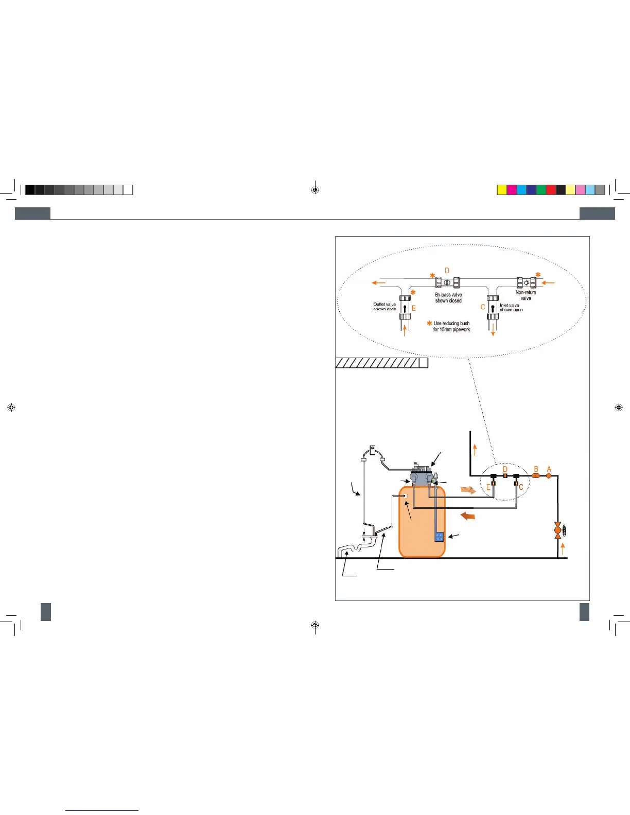
3.4 Installation Layout
Water softener
K. Over ow exible hose
Key to the diagram:
A. Non return valve
B. Pressure reducing valve (where required)
C. Inlet valve ¾“
D. Bypass valve
E. Outlet valve ¾“
G. Brine storage cabinet
Observe a minimum distance to the ceiling (N) of 0.5 m.
J. Drainage (
* Existing or new “Trapped“ stand pipe or to external drainage)
H. Fixing clip
20 mm
Key to the diagram:
H. Fixing clip
I. Waste water hose
J. Drainage
K. Flexible hose, Over ow
L. Control valve (green)
M. Servo-motor for valve positioning
N. Distance device & ceiling of room
O. Over ow connection ½“
P. Waste water trap
E. OutletL.
N.
P.
OPM - Cillit Access 10-25 vOrange - EN, DEv4.indd 10-11 02/10/2012 09:48