13
EN
12
EN
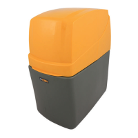
3.5 Technical overview of device:
C. Inlet connection (feed water) for exible hose, with thread ¾“
E. Outlet connection (softened water) for exible hose, with thread ¾“
G1. Brine storage cabinet salt lling
G2. Connection to brine internal connection
O. Over ow connection for exible hose, threadless ½“
L. Control valve ow regulation
M. Servo motor for control valve
I. Waste water connection external drainage of waste water
Attention: Pipework sized min. DN50. Use only the exible hoses included in the delivery.
Ensure a correct sealing and setting of all pipes before rst commissioning.
Attention: To comply with good plumbing practice the external waste-water-drainage must have a mini-
mum space of air: 20 mm (according to guideline EN 14743).
Attention: Drainage from the over ow of the brine tank, Connections between the channel and two exible
hoses (according to standard EN 3131).
Protection of device: To increase the lifetime of your softener ensure it is kept in a clean, dry place with an
ambient temperature between 5 and 40 °C. Do not mention damage to resin or components.
I.
C.
E. G1.
L.
O.
G2.
C.
M.
L.
E.
I.
3.6 Installing your softener
1. Positioning the water softener
It is very important to establish the water pressu-
re before installing the water softener. If the water
pressure is low then the water softener may not
operate effectively. If it is too high, then compo-
nents inside the unit may be damaged.
Water pressure should be tested with a gauge at
the kitchen tap or outside tap. It should be noted
that water pressure can increase at periods of
low water usage e.g. overnight. If therefore, the
daytime pressure exceeds 5.0 bar UK, 8.0 bar
EU or if you are unsure about pressure, then a
pressure reducing valve should be tted.
Where the pressure is less than 1.7 bar UK, 1.0
bar EU a booster pump may be required.
2. Inlet and outlet connections
With the bypass valve open and the inlet / outlet
valves closed the unit can be connected to the plum-
bing system. Arrows on the inlet and outlet piping
from the valve will con rm the direction of ow.
Connections can be made with either conventional
copper tube and ttings or the high ow exible ho-
ses supplied, ensure hoses are not kinked as this
may restrict ow.
3. Drain connection
Push the exible drain hose onto the barbed con-
nector (Drain) as shown on page 7 and secure with
the clip provided. Run the drain hose to a stand
pipe or to a drain. The air gap needs to be at least
20 mm. Softened water will have no adverse effect
on a septic tank. You can extend the drain up to 9m
if you have suf cient pressure (greater than 3 bar).
The drain hose must not be kinked or restricted in
any way as this will cause an over ow from the bri-
ne cabinet.
Frost protection
If the drain hose or connecting pipework is likely
to be subject to temperatures below 0°C it must
be protected to prevent freezing. Failure to obser-
ve this precaution could lead to the water softener
over owing.
Raising the drain hose
If you have a water pressure of 3 bar or more, you
can raise the drain to a maximum of 3 metres abo-
ve the valve head.
4. Over ow connections
The hose barb over ow pipe (not supplied with the
softener) should be connected to the push t elbow
at the rear of the cabinet (see page 9).
Run the pipe downhill to the drainage. Take care
that the over ow does not discharge where dama-
ge could occur.
If the water softener is tted in a cellar or basement,
the over ow can be run to a storage tank. Do not
elevate the over ow hose.
Note: Do not use jointing cement on the tting.
5. Electrical connections
For added safety, peace of mind and ease of in-
stallation, your water softener is powered by low
voltage via a plug in transformer. This transformer
must be connected to a switched socket.
Attention: Plug the transformer into the socket
with the switch in the OFF-position.
6. Filling the brine cabinet, salt- usage and alarm
Now place the water softener salt in the brine ca-
binet. Use the care cubes (tablet salt) or block salt
(UK), from your local dealer.
Notes on salt usage: Your water softener will only
perform effectively if there is salt in the brine cabi-
net during the regeneration process.
It is therefore essential that the salt level does not
fall lower than 150mm in depth when measured
from the base of the brine cabinet. N.B. The sof-
tener requires no priming, add no water to the
brine tank. During regeneration, salt will not enter
your water system as the salt used in the regenera-
tion process is rinsed safely away to drain.
Salt alarm is optional - not standard on most
models. Depending on your model your water
softener may be equipped with a low salt alarm,
this monitors your salt usage and sounds an audi-
ble alarm while displaying the low salt error code
“SALt“ when your salt levels falls to the minimum
level. To reset the salt alarm ll the system with
salt and press the SET-key.
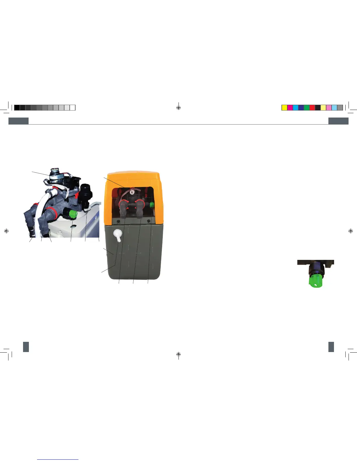
7. Blending control
All machines are fac-
tory set to produce
water that is soft.
Note: If you prefer wa-
ter which is less soft,
turn the blending knob
on the left side of the
valve anti-clockwise
until the water meets your requirements.
8. Testing for the water hardness in your area
Water hardness can vary from one location to
another. To determine the hardness of the water
feeding your water softener (unsoftened supply)
use the hardness test kit supplied.
• Fill the test bottle supplied to the ll line with
water from a hard water tap.
OPM - Cillit Access 10-25 vOrange - EN, DEv4.indd 12-13 02/10/2012 09:48
 Loading...