Manuale Istruzioni
Instruction Manual
3.3. CONNESSIONE COMPUTER 3.3. CONNECTING TO A COMPUTER
La MAXIMA 841 viene fornita con il cavo di
collegamento seriale lungo 2,5 metri. Se tale
lunghezza risulta insufficiente occorre realizzare una
prolunga prendendo i provvedimenti necessari a
garantire la dovuta immunità ai disturbi
MAXIMA 841 is supplied with a 2,5 m serial cable.
If this length is insufficient an extension can be
added taking the necessary actions to ensure the
necessary noise immunity.
3.4. AVVERTENZE E CAUTELE DI
INSTALLAZIONE
3.4. WARNINGS AND ADVISE
DURING THE INSTALLATION
•
La targhetta di identificazione situata nel
pannello posteriore oltre ad indicare il numero di
serie e il tipo di macchina indica la tensione di
alimentazione e la corrente assorbita, pertanto
verificare che la sorgente dì alimentazione risulti
come specificato.
•
Prima di attivare la macchina assicurarsi che tutti
i cavi siano correttamente collegati e che la
tensione di rete corrisponda ai valori di targa. La
targhetta è schematizzata come segue:
•
The Identification plate attached to the rear panel
contains information about the serial number, the
type of machine, the necessary power supply and
the absorbed current. Thus one should verify that
the local power supply corrisponds to that stated
on the plate.
•
Before switching the machine on be sure that all
the cables have been connected correctly and
that the local power supply corrisponds to that
stated on the plate. The plate layout is as follows:
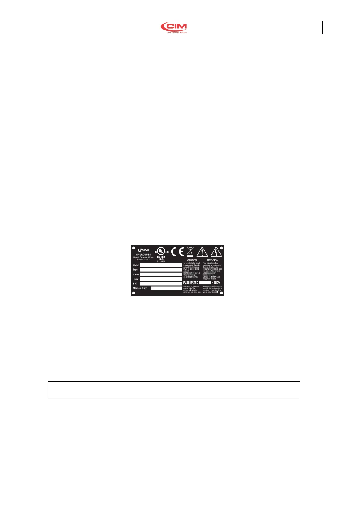
Dopo la ragione sociale la
targhetta presenta 6 campi
punzonati così indicati:
•
Model : Modello della macchina
•
Type : Tipo di punzonatura
•
Volt : Tensione di Rete
•
Hz : Frequenza di Rete
•
A : Corrente massima ass.
•
SN : Matricola
After the Trade name the plate has
6 embossed fields as shown
below:
•
Model : Machine model
•
Type : Embossing mode
•
Volt : Power Supply
•
Hz : Frequenzy supply
•
A : Power absorbed
•
SN : Serial Number
Fig. 4
3.5. ACCENSIONE E VERIFICA 3.5. SWITCHING ON AND
CONTROLLING THE DISPLAY
Una volta installata, la macchina può essere
accesa mediante l’interuttore generale e sul display
dovrà apparire il messagio di fig.5
Once installed the machine can be switched on with
main switch, on display will appear the message as
fig.5
E-00 POWER ON STAND BY STATUS - PRESS START
Fig. 5
Premere il pulsante di START sul pannello frontale
a fianco del display per eseguire il reset generale. A
fine ciclo sul display appare il messaggi di fig.6 per
indicare lo stato attivo dellla macchina.
Press the START key on right side of the front
panel beside the display. This activates a general
reset which, when completed, will leave another
message (Ref. Fig 6) on the display to indicate the
Ready State of the machine.