43
Number Color Function
1 Red MA4 Electronic Control Unit Power (+)
2 Green/Yellow Stripe MA4 Electronic Control Unit Power (-)
3 Red/Black Stripe Burner Power
4 Red Battery (+)
5 White Burner Enable
6 Red Micro Panel Accessory Input
7 Green/Yellow Stripe Battery (-)
9 Red Accessory Relay Output
10 Red Relay Panel Lug to Fuse
11 Red Fuse to Relay
13 Red Fuse to Auto Switch
14 Red Terminal Strip to Hose Controller and Controller Strip
17 Green/Yellow Stripe Ground (ALL GROUND SYMBOLS ON DRAWING)
18 Pink Material Controller to Burner Relay
19 White Sensor Wire Controller to Terminal Strip
20 Red Sensor Wire Controller to Terminal Strip
21 White Sensor Wire Terminal Strip Thermocouple
22 Red Sensor Wire Terminal Strip to Thermocouple
23 Blue/White Stripe Clean Out
24 Green/ White Stripe Material Temp Ready
28 Red Manifold Switch to Rotary
29 Gray Oil Controller to Agitator Manifold
30 Purple Material Controller to Pump Manifold
31 Gray Oil Controller to Material Controller
32 Tan Manifold to Switch
33 Gray Manifold to Agitator Switch
34 Green Manifold to Rotary Switch #3
35 Purple Manifold to Pump Switch
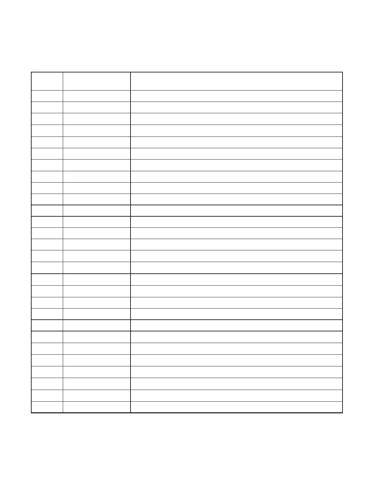
MA4 Control Panel Wiring Diagram