15
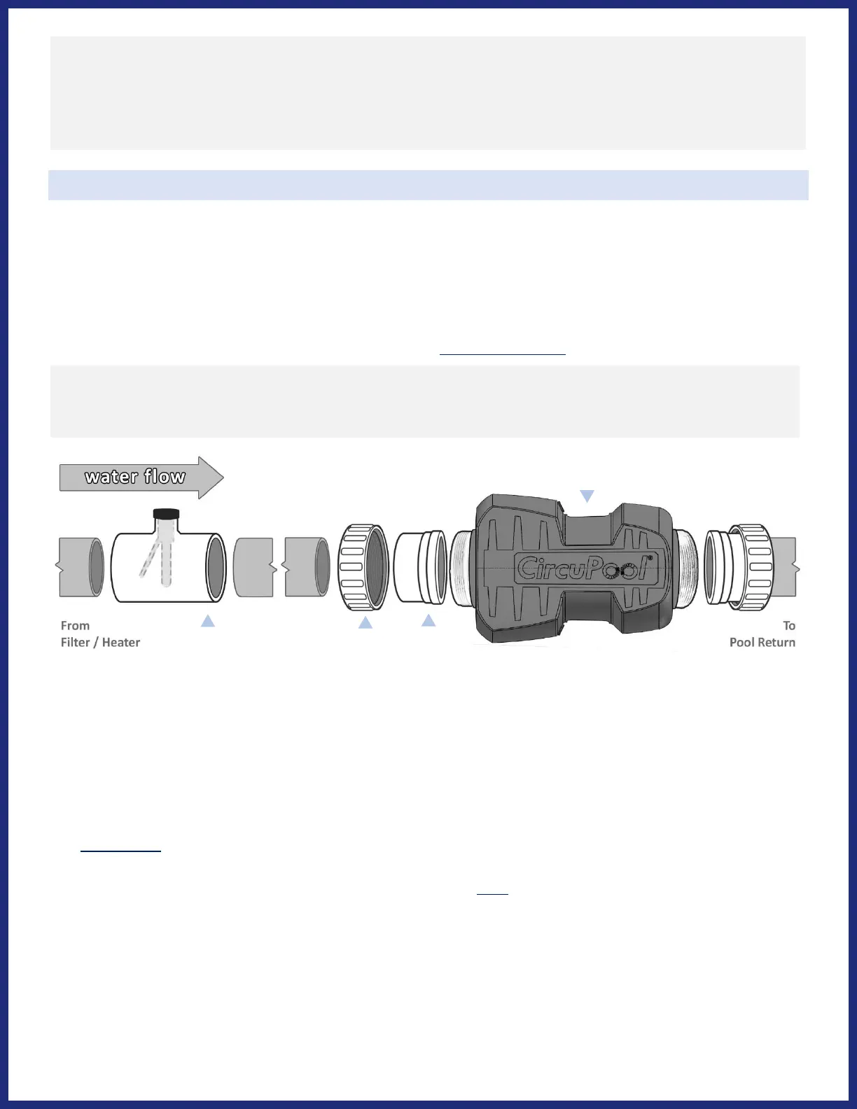
Installing the Electrolytic Cell and Flow Switch
The Cell and Flow Switch are to be fitted into the return line (horizontally or vertically) as the last pieces of equipment the
water passes through before returning to the pool: always after the pump, filter, heater (if applicable), etc. If a heater is
present, all equipment must be a minimum distance away, per heater manufacturer recommendations.
Refer to the overview diagram on page 14 for alternate configurations. For combined pool and spa systems with a spillover,
configurations #2 or #3 allow chlorination for both the pool and spa during spillover but preventing possible over-
chlorination when operating the spa only. Vertical Installation Kits are also available to minimize plumbing space required
and increase ease of installation (sold separately, available at www.circupool.com).
1. Lay out your equipment to ensure there is enough pipe space available.
2. On the pipe where the Cell will be installed, mark two lines 11” apart and then cut the pipe (for 2” plumbing).
3. Unscrew and removed Threaded Collars from Cell. Slide these over the pipe on each side of the cut, then glue each
Union to the cut pipe. Ensure O-Rings are in place on Unions.
- TIP: Glue one Union first, then when gluing second Union use Cell body to gauge the final distance need between
each Union; make small adjustments to second union’s slip connection while glue is still wet.
4. Only after the glue has fully cured, place the Cell into the opening between Unions and tighten the Threaded Collars
(by hand only) to ensure that the Cell fits securely in place. DO NOT OVER-TIGHTEN.
5. Install the Flow Switch next to the Cell. Ensure that any excess glue does not become contact with movable switch.
- IMPORTANT: If positioning the Flow Switch horizontally, you must orient the wires to be facing upwards.
• This portion is threaded and can be turned during service to align arrow with water flow; additional thread seal
tape may be added if necessary.
- IMPORTANT: When positioning the Flow Switch, ensure that there is no valve between the Cell and Flow Switch.
- IMPORTANT: When positioning the Flow Switch, it should be upstream from the cell and there must be at least 6 to
12” (30cm) of straight pipe before the Flow Switch.
- To ensure proper operation, verify that the arrow on the flow switch points in the direction of water flow; the
water flow must depress the hinged activator inside of the Flow Switch.
CAUTION: Ensure that the pool pump and all electrical power are turned off before installation.
TIP: Lay out your equipment and wiring to confirm placement and measurements first before cutting and gluing.
TIP: Be sure to clean & smooth cut pipe. When gluing PVC, parts will slip in place easier once glue is applied. Be sure
to apply firm, constant pressure between both glued parts for up to a minute to prevent potential slippage.