18
Note: From the supplied components, select the plumbing fittings that
match the existing pool plumbing size (1 ½” or 2”). Discard unneeded
fittings. For installations using 1 ½" Cell Unions, you will also use 2"-to-1
½" reducer bushings with flow switch. Be sure to note any new or
additional measurements before cutting pipe.
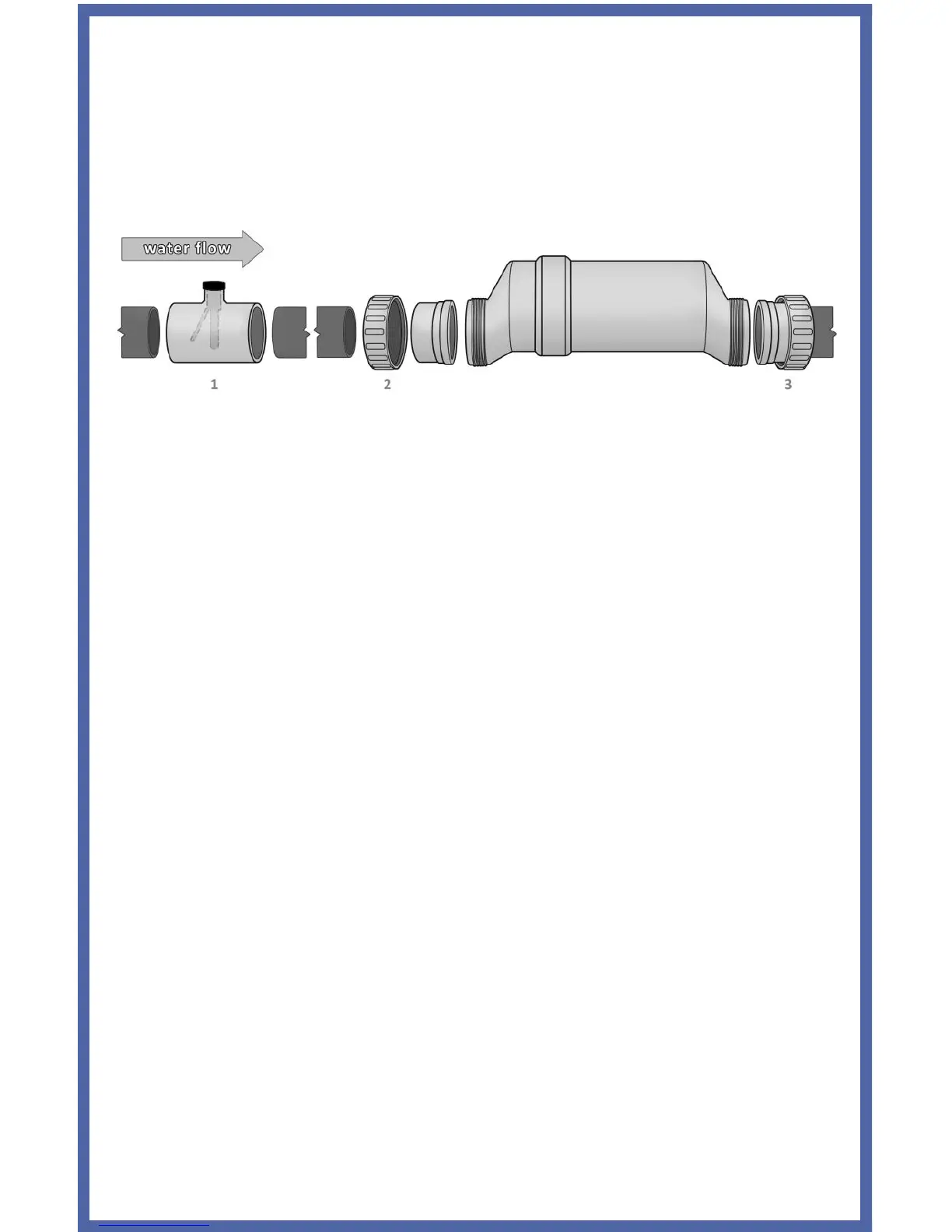
After determining the section of plumbing to install the Flow Switch and
Cell, measure out and mark the selected area.
1. To install the Flow Switch, cut out a section of pipe at the desired
installation location. Use PVC Primer to clean and prepare the pipe
ends and interior of Flow Switch. Using plumbing Solvent Cement,
glue the Flow Switch to the pipe ends. Ensure excess glue does not
become affixed to movable parts within Flow Switch. IMPORTANT:
To insure proper operation, verify that the arrow on the flow switch
(located on the black plastic) points in the direction of water flow;
the water flow must depress the hinged activator inside of the Flow
Switch. This portion is threaded and can be turned during service;
additional thread seal tape may be added if necessary.
2. To install the Cell Unions, cut out a section of pipe at the desired
installation location. Clean parts and plumbing with PVC Primer to
prepare the pipe ends and interior of Unions. Place the Threaded
Collars over the pipe ends. Using plumbing Solvent Cement, glue
one Union to the pipe end.
3. Hold the Cell and second Union up to the first, to gauge the correct
distance before gluing the second Union to the remaining pipe end.
If the distance does not appear to be correct, make any needed
adjustments, then glue remaining union. Allow sufficient time for
glue to dry.
Ensure that the O-rings are fitted to the Unions. Place the Electrolytic Cell
between the Unions and tighten the Collars onto the Cell. For a watertight
seal, do not over-tighten the Collars, and only tighten them by hand.