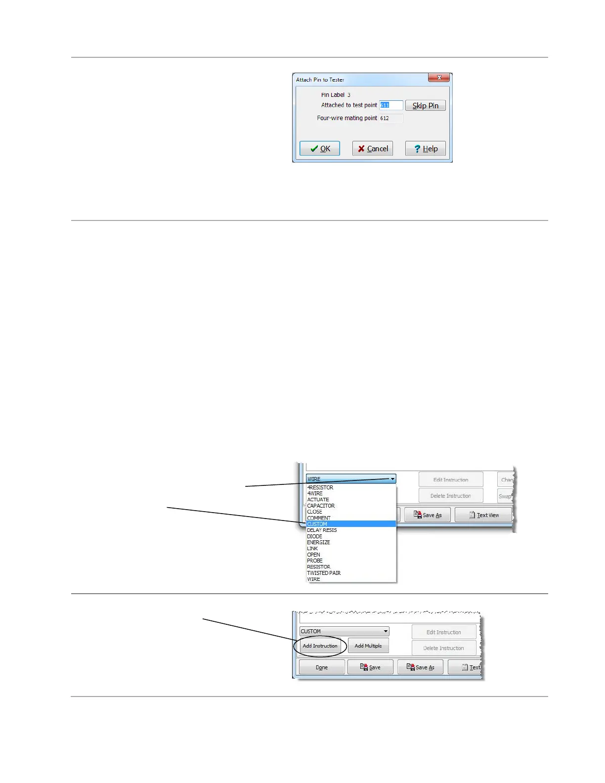
The pins the “External Instrument-16”
connector are being attached as four-wire
points. Every odd numbered pin has a
corresponding adjacent even numbered
four-wire point.
3. Click OK to accept each of the odd
numbered pins in the External Instrument-
16 connector. After you click OK for the
last pin, the dialog box disappears. The
connector is attached.
Setting up an Attach Custom Instruction
Whenever you use the external instrument in a test program, you must use an “attach custom instruction”
before using other external instrument custom instructions. The attach custom instruction tells the tester
how pins from the CH2 external instrument connector are wired or mapped to the connections on the
external instrument.
There is both a 2-wire and 4-wire custom attach instruction. If you want to use a 2-wire test instruction, you
must use a 2-wire attach instruction first in test program. Likewise, if you want to use a 4-wire test
instruction, you must first use a 4-wire attach instruction in test program. Pins 25 and 27 of the external
instrument connector are used for the 4-wire attach instruction. Pins 29 and 31 are used for 2-wire attach
instruction.
WARNING! If you are using the External Instrument Cable from Cirris (see page 7), include both
the 2-wire AND the 4-wire instructions to the test program. Add both instructions even if you are
not performing 4-wire testing. If the 4-wire instruction is not included, the hipot portion of the test
could damage your meter. For further questions or concerns, contact Cirris.
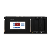
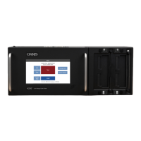
To set up an attach instruction:
1. In the “Define Instructions” tab of
the “Test Program Editor.” Click
the instruction drop down box, and
select Custom.