7-6 P/N 13999-002 Info Manual
Section 7 Cirrus Design
Airplane Description SR20
Airframe
Fuselage
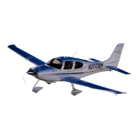
The SR20 monocoque fuselage is constructed primarily of composite
materials and is designed to be aerodynamically efficient. The cabin
area is bounded on the forward side by the firewall at fuselage station
100, and on the rear by the aft baggage compartment bulkhead at
fuselage station 222. Comfortable seating is provided for four adults. A
composite roll cage within the fuselage structure provides roll
protection for the cabin occupants. The cabin and baggage
compartment floors are constructed of a foam core composite with
access to under-floor components.
All flight and static loads are transferred to the fuselage structure from
the wings and control surfaces through four wing attach points in two
locations under the front seats and two locations on the sidewall just
aft of the rear seats.
• Note •
Refer to Airplane Cabin description in this section for a
complete description of doors, windows, baggage
compartment, seats, and safety equipment.
Wings
The wing structure is constructed of composite materials producing
wing surfaces that are smooth and seamless. The wing cross section
is a blend of several high performance airfoils. A high aspect ratio
results in low drag. Each wing provides attach structure for the main
landing gear and contains a 30.25-gallon fuel tank.
The wing is constructed in a conventional spar, rib, and shear section
arrangement. The upper and lower skins are bonded to the spar, ribs,
and shear sections (rear spars) forming a torsion box that carries all of
the wing bending and torsion loads. The wing spar is manufactured in
one piece and is continuous from wing tip to wing tip. The shear webs
(rear spars) are similar in construction but do not carry through the
fuselage. The main wing spar passes under the fuselage below the
two front seats and is attached to the fuselage in two locations. The
rear shear webs are attached to the fuselage sidewalls just aft of the
rear seats.
September 2011

 Loading...