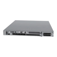
Figure 11: 6-Port 1/10/25-Gb Network Module (FPR3K-XNM-6X1SXF, FPR3K-XNM-6X10SRF, FPR3K-XNM-6X10LRF, FPR3K-XNM-6X25SRF,
and FPR3K-XNM-6X25LRF)
Ethernet 2/3 (top port)
Ethernet 2/4 (bottom port)
Ports 3 and 4 are paired together to form a
hardware bypass pair.
2Ethernet 2/1 (top port)
Ethernet 2/2 (bottom port)
Ports 1 and 2 are paired together to form a
hardware bypass pair.
1
Ethernet 2/7 (top port)
Ethernet 2/8 (bottom port)
Ports 7 and 8 are paired together to form a
hardware bypass pair.
4Ethernet 2/5 (top port)
Ethernet 2/6 (bottom port)
Ports 5 and 6 are paired together to form a
hardware bypass pair.
3
Ethernet 2/11 (top port)
Ethernet 2/12 (bottom port)
Ports 11 and 12 are paired together to form a
hardware bypass pair.
6Ethernet 2/9 (top port)
Ethernet 2/10 (bottom port)
Ports 9 and 10 are paired together to form a
hardware bypass pair.
5
Captive screw8Bypass LEDs B1 through B3:
• Off—Bypass mode is disabled.
• Green—Port is in standby mode.
• Amber, flashing—Port is in hardware bypass
mode, failure event.
7
Handle ejector10Power LED9
Cisco Secure Firewall 3100 Series Hardware Installation Guide
23
Overview
6-Port 1-Gb SX/10-Gb SR/10-Gb LR/25-Gb SR/25-Gb LR Network Module with Hardware Bypass

 Loading...