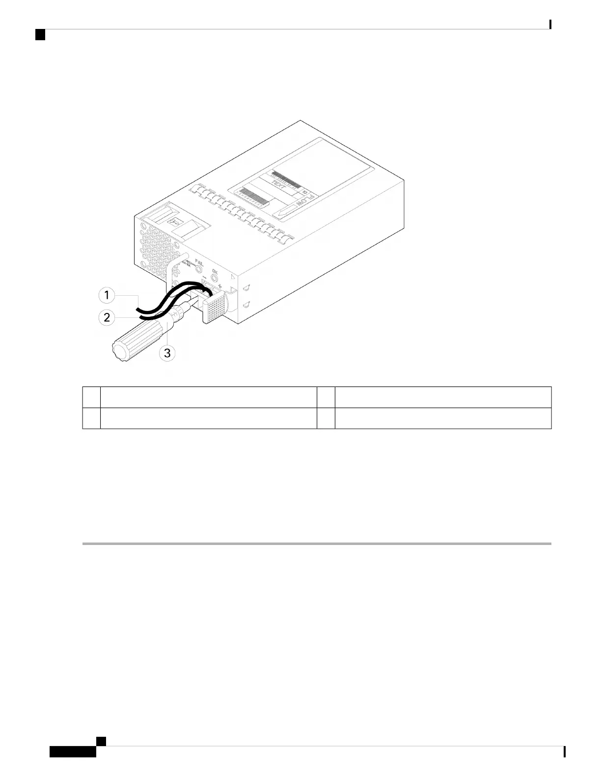
Figure 52: Tighten the Terminal Block Captive Screws
Positive (+) lead wire2Negative (-) lead wire1
—Screwdriver3
Step 6 Repeat these steps for the remaining DC input power source wire as applicable.
Step 7 Use a tie wrap so secure the wires to the rack, so that the wires are not pulled from the terminal block.
Step 8 Set the DC disconnect switch in the circuit to ON. In a system with multiple power supplies, connect each power supply
to a separate DC power source. In the event of a power source failure, if the second source is still available, it can maintain
system operation.
Step 9 Verify power supply operation by checking the power supply LED on the front of the chassis. See Front Panel LEDs, on
page 11 for the LED values.
Secure the Power Cord on the Power Supply Module
To secure the power supply module against accidental removal and thus prevent disrupting system performance,
use the tie wrap and clamp provided in the accessories kit that ships with your Secure Firewall 3100 series.
Safety Warnings
Take note of the following warnings:
Cisco Secure Firewall 3100 Series Hardware Installation Guide
76
Installation, Maintenance, and Upgrade
Secure the Power Cord on the Power Supply Module
 Loading...