Platform Components
Cisco 3504 Wireless Controller Front Panel
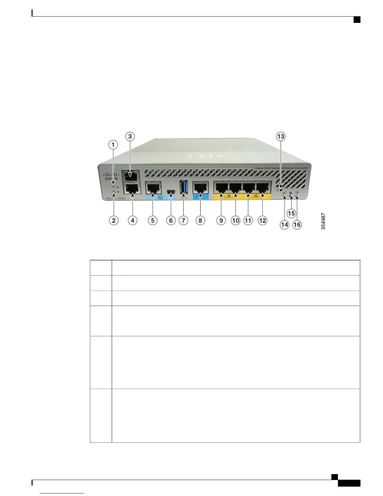
Figure 2: Cisco 3504 Wireless Controller Front Panel View
Table 2: Cisco 3504 Wireless Controller Front Panel Components
Service Port LED1
Redundancy Port LED2
Service Port (SP) (RJ-45) for out-of-band management3
Redundancy Port (RP) (RJ-45).
The redundancy ports can be connected back to back or via an L2
switch.
Note
4
CPU console port, which is an RS-232 port that supports an RJ-45 connector. At boot-up, the
controller configures the RS-232 port as a console port with default settings of 9600, N, 8, 1. The
boot-loader supports baud rates of 1200, 2400, 4800, 9600, 19200, 38400, 57600, and 115200. A
default baud-rate recovery mechanism is not available; however, the bootloader ensures that the
stored baud rate setting matches one of the allowed values before setting the baud rate. If a
nonstandard value is detected, the baud rate will default to 9600.
5
Mini-B USB console port that can be used to perform software updates in addition to the already
available transfer modes, namely HTTP, TFTP, FTP, and SFTP.
If the Mini-B USB console port is used, the CPU console port that supports RJ-45 connector
is ignored. That is, only one of the two ports are ever active.
If you connect to both Mini-B USB port and the CPU console port, then the CPU console
port takes precedence.
Note
6
Cisco 3504 Wireless Controller Installation Guide
3
Overview of Cisco 3504 Wireless Controller
Platform Components