3-13
Catalyst 3750 Switch Hardware Installation Guide
78-15136-01
Chapter 3 Switch Installation
Planning the Stack
Cabling Considerations
The illustrations in this section display cabling configuration examples that show
the stack bandwidth and possible stack partitioning.
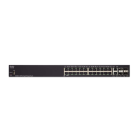
Figure 3-2 shows an example of a stack of Catalyst 3750 switches that provides
full bandwidth and redundant connections.
Figure 3-2 Example of a Stack with Full Bandwidth Connections
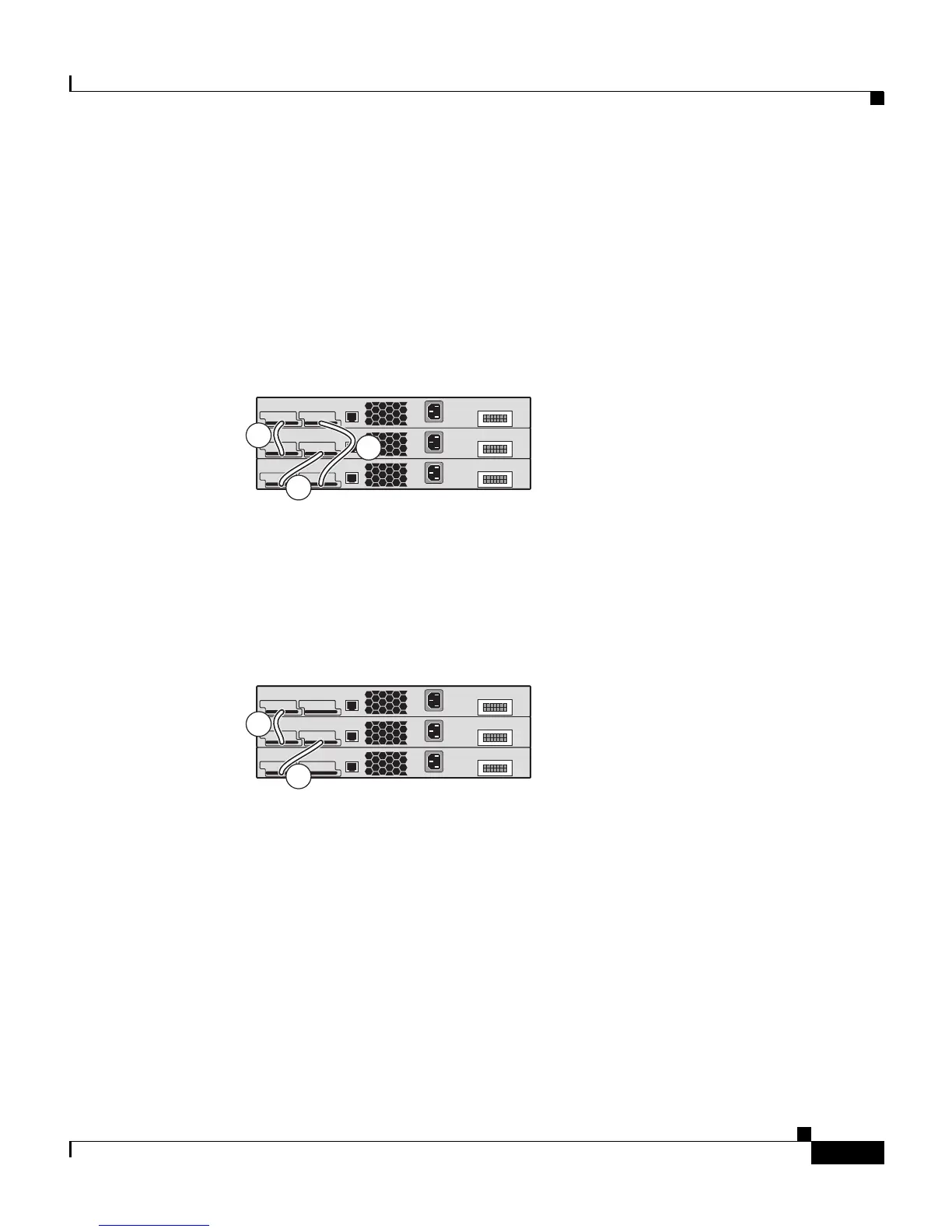
Figure 3-3 shows an example of a stack of Catalyst 3750 switches with
incomplete cabling connections. This stack provides only half bandwidth and
does not have redundant connections.
Figure 3-3 Example of a Stack with Half Bandwidth Connections
Figure 3-4 and Figure 3-5 show examples of stacks of Catalyst 3750 switches
with failover conditions. In Figure 3-4, the cable is bad in link B, therefore this
stack provides only half bandwidth and does not have redundant connections. In
Figure 3-5 link B is bad; therefore, this stack partitions into two stacks with
switch 1 and switch 3 being stack masters.
86821
A
86823
A