A-3
Cisco Secure Router 520 Series Hardware Installation Guide
OL-12892-01
Appendix A Specifications
Console Connector Pinouts
Console Connector Pinouts
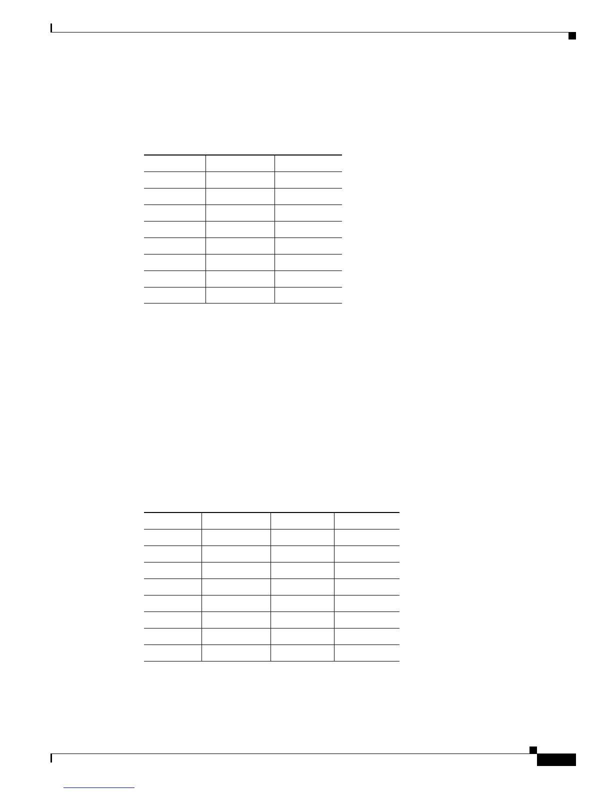
Table A-3 provides pinouts for the console connector (for connecting a terminal or PC).
Ta b l e A-3 Console Connector Pinouts (RJ-45-to-DB-9)
RJ-45 Pin Function DB-9 Pin
1 RTS 8
2 DTR 6
3 TXD 2
4 GND 5
5 GND 5
6 RXD 3
7 DSR 4
8 CTS 7
The console port is configured as a data communications equipment (DCE) device. The default
parameters for the console port are as follows:
• 9600 baud
• 8 data bits
• No parity
• One stop bit
ADSL Port Connector Pinouts
Table A-4 provides the ADSL connector pinouts.
Ta b l e A-4 ADSL Connector Pinouts (RJ-11-to-RJ-45)
RJ-11 Pin Function RJ-45 Pin Function
1 Unused 1 Unused
2 Unused 2 Unused
3 Ring 3 Unused
4 Tip 4 Ring
5 Unused 5 Tip
6 Unused 6 Unused
7 Unused
8 Unused