Chapter 3 Installing the ASA 5550
Ports and LEDs
3-10
Cisco ASA 5500 Series Getting Started Guide
78-19186-01
Rear Panel LEDs and Ports in Slot 0
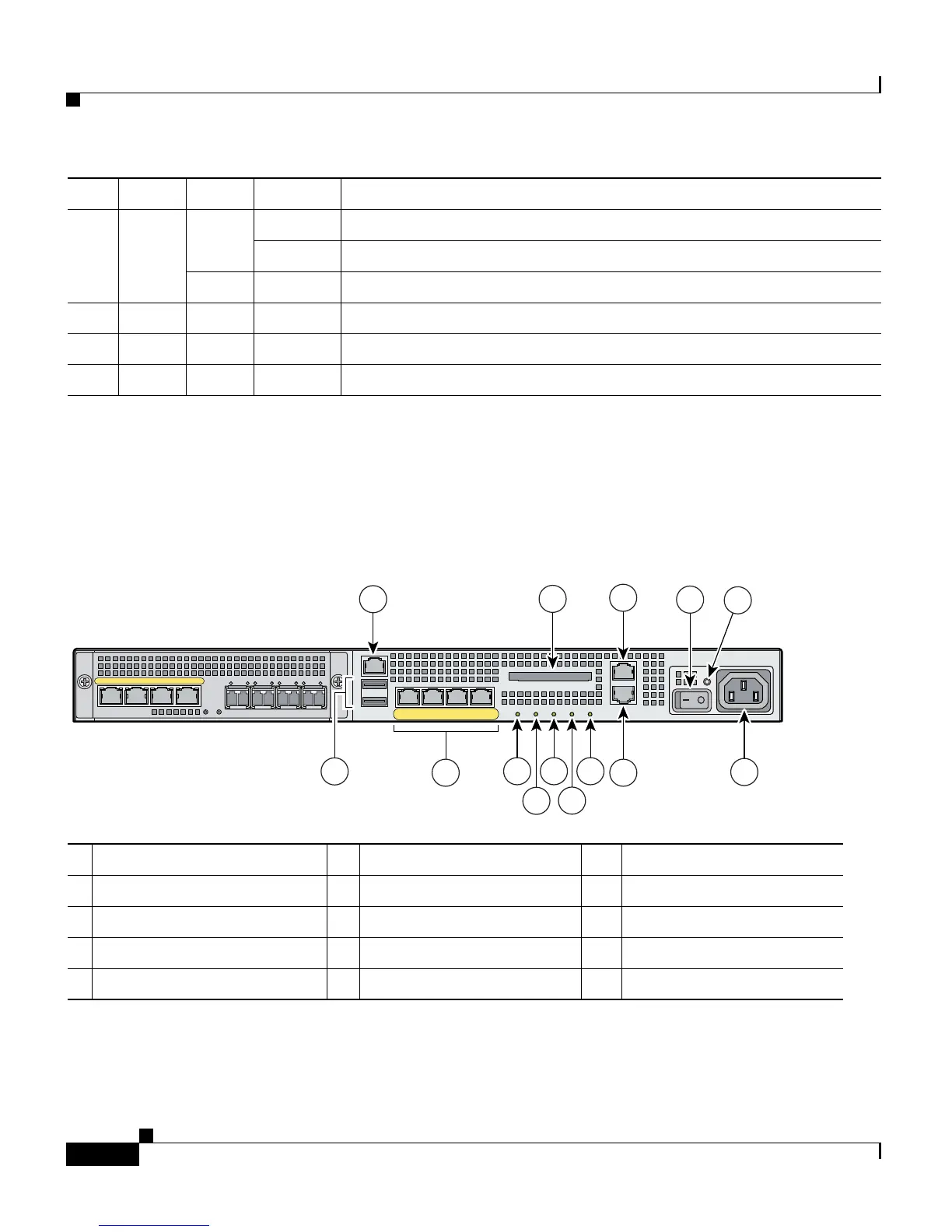
Figure 3-6 shows the rear panel LEDs and ports in Slot 0.
Figure 3-6 Rear Panel LEDs and Ports on Slot 0 (AC Power Supply Model Shown)
2 Status Green Flashing The power-up diagnostics are running or the system is booting.
Solid The system has passed power-up diagnostics.
Amber Solid The power-up diagnostics have failed.
3 Active Green Flashing There is network activity.
4 VPN Green Solid VPN tunnel is established.
5 Flash Green Solid The CompactFlash is being accessed.
LED Color State Description
1 Management Port
1
1. The management 0/0 interface is a Fast Ethernet interface designed for management traffic only.
6 USB 2.0 interfaces
2
2. Reserved for future use.
11 VPN LED
2 External CompactFlash slot 7 Network interfaces
3
12 Flash LED
3 Serial Console port 8 Power indicator LED 13 AUX port
4 Power switch 9 Status indicator LED 14 Power connector
5 Power indicator LED 10 Active LED
153103
LINK SPD
2
LINK SPD
1
LINK SPD
0
LINK SPD
3
MGMT
USB2
USB1
FLASH
CONSOLE
AUX
POWER
STATUS
FLASH
1
9
2
3
4
5
11
13
14
7
8 10 12
VPN
ACTIVE
PWR
STATUS
LNK
SPD0123
6

 Loading...