3-11
Cisco ASA 5500 Series Getting Started Guide
78-19186-01
Chapter 3 Installing the ASA 5550
Ports and LEDs
For more information on the Management Port, see the management-only
command in the Cisco ASA 5500 Series Command Reference.
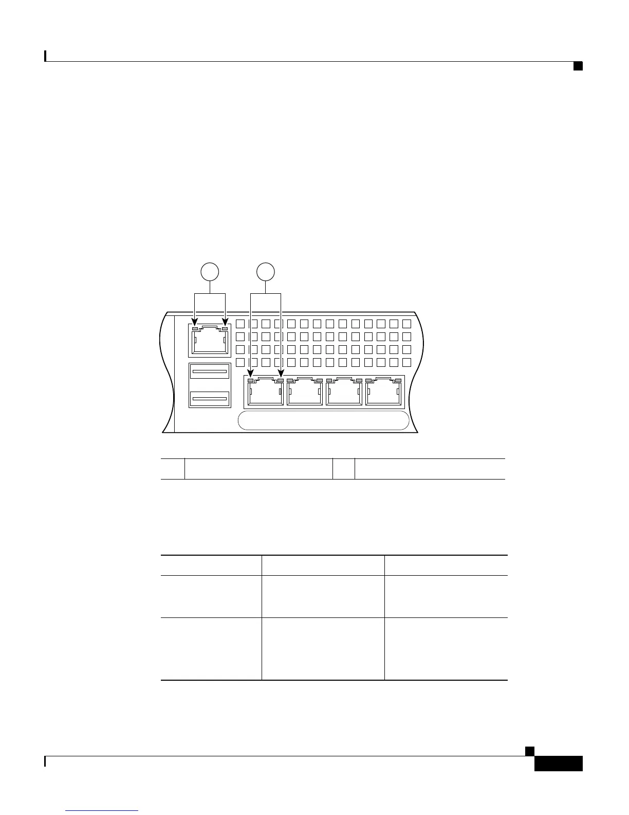
Figure 3-7 shows the adaptive security appliance rear panel LEDs.
Figure 3-7 Rear Panel Link and Speed Indicator LEDs
Table 3-3 lists the rear MGMT and Network interface LEDs.
3. GigabiteEthernet interfaces, from right to left, GigabitEthernet 0/0, GigabitEthernet 0/1, GigabitEthernet 0/2, and
GigabitEthernet 0/3.
1 MGMT indicator LEDs 2 Network interface LEDs
126917
USB2
USB1
LNK SPD
3
LNK SPD
2
LNK SPD
1
LNK SPD
0
MGMT
21
Ta b l e 3-3 Link and Speed LEDs
Indicator Color Description
Left side Solid green
Green flashing
Physical link
Network activity
Right side Not lit
Green
Amber
10 Mbps
100 Mbps
1000 Mbps

 Loading...