Chapter 3 Installing the ASA 5550
Ports and LEDs
3-12
Cisco ASA 5500 Series Getting Started Guide
78-19186-01
Ports and LEDs in Slot 1
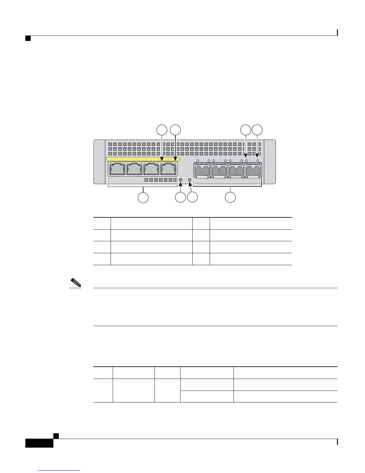
Figure 3-8 illustrates the ports and LEDs in Slot 1.
Figure 3-8 Ports and LEDs in Slot 1
Note Figure 3-8 shows SFP modules installed in the fiber Ethernet ports. You must
order and install the SFP modules if you want to establish fiber Ethernet
connectivity. For more information on fiber ports and SFP modules, see the
“Installing SFP Modules” section on page 3-6.
Table 3-4 describes the LEDs in Slot 1.
1 Copper Ethernet ports 5 Status LED
2 RJ-45 Link LED 6 Fiber Ethernet ports
3 RJ-45 Speed LED 7 SFP Link LED
4 Power LED 8 SFP Speed LED
153212
PWR
STATUS
LNK
SPD0123
Cisco SSM-4GE
4
1
6
5
7
8
2
3
Ta b l e 3-4 LEDs on Bus G1
LED Color State Description
2, 7 LINK Green Solid There is an Ethernet link.
Flashing There is Ethernet activity.

 Loading...