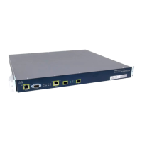
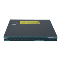
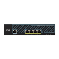
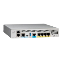
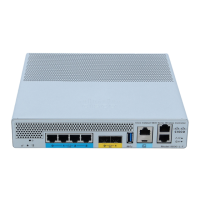
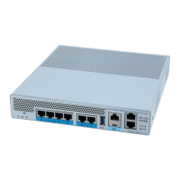
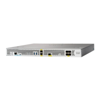
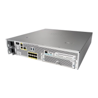
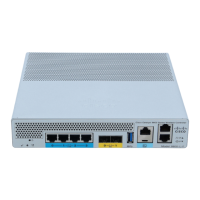
To ensure proper airflow it is necessary to rack the controllers using rail kits. Physically placing the units
on top of one another or “stacking” without the use of the rail kits blocks the air vents on top of the
controllers, which could result in overheating, higher fan speeds, and higher power consumption. We
recommend that you mount your controllers on rail kits when you are installing them into the rack because
these rails provide the minimal spacing required between the controllers. No additional spacing between
the controllers is required when you mount the units using rail kits.
The rail mounting kit (Part Number: UCSC-RAILB-M4=) is provided along with the Cisco 5520 WLC
and you do not have to order it separately.
Caution
Avoid UPS models that use ferroresonant technology. These UPS models can become unstable with
systems such as the Cisco UCS, which can have substantial current draw fluctuations from fluctuating
data traffic patterns.
Caution
Rack Requirements
This section provides the requirements for the standard open racks.
The rack must be of the following type:
•
A standard 19-in. (48.3-cm) wide, four-post EIA rack, with mounting posts that conform to English
universal hole spacing, per section 1 of ANSI/EIA-310-D-1992.
•
The rack post holes can be square 0.38-inch (9.6 mm), round 0.28-inch (7.1 mm), #12-24 UNC, or
#10-32 UNC when you use the supplied slide rails.
•
The minimum vertical rack space per controller must be one RU, equal to 1.75 in. (44.45 mm).
Equipment Requirements
The slide rails sold by Cisco Systems for this controller do not require tools for installation.
Slide Rail Adjustment Range
The slide rails for this controller have an adjustment range of 24 to 36 inches (610 to 914 mm).
Installing the Controller in a Rack
Installing the Slide Rails
This section describes how to install the controller in a rack using the rack kits that are sold by Cisco Systems.
Cisco 5520 Wireless Controller Installation Guide
3
Installing the Cisco 5520 Wireless Controller
Rack Requirements
 Loading...
