c) Slide the release clip toward the rear on both inner rails, and then continue pushing the controller into the rack until
its front slam latches engage with the rack posts.
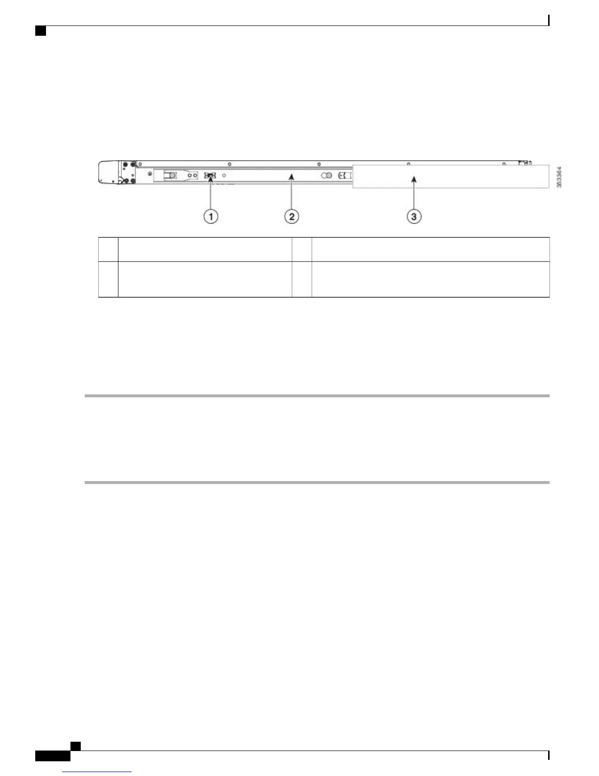
Figure 3: Inner Rail Release Clip
Outer rail attached to rack post3Inner rail release clip1
Inner rail attached to controller and inserted
into outer rail
2
Step 5
(Optional) Secure the controller in the rack more permanently by using the two screws that are provided with the slide
rails. Perform this step if you plan to move the rack with controller installed.
With the controller fully pushed into the slide rails, open a hinged slam latch lever on the front of the controller and
insert the screw through the hole that is under the lever. The screw threads into the static part of the rail on the rack post
and prevents the controller from being pulled out. Repeat for the opposite slam latch.
Installing the Cable Management Arm (Optional)
Step 1
With the controller pushed fully into the rack, slide the CMA tab of the CMA arm that is farthest from the controller
onto the end of the stationary slide rail that is attached to the rack post (see Attaching the Cable Management Arm to the
Rear of the Slide Rails). Slide the tab over the end of the rail until it clicks and locks.
The CMA is reversible left to right. To reverse the CMA, see Reversing the Cable Management Arm (Optional)
before installation.
Note
Cisco 5520 Wireless Controller Installation Guide
6
Installing the Cisco 5520 Wireless Controller
Installing the Cable Management Arm (Optional)

 Loading...