On the outside of the assembly, push the green arrow button towards the rear to open the securing plate.
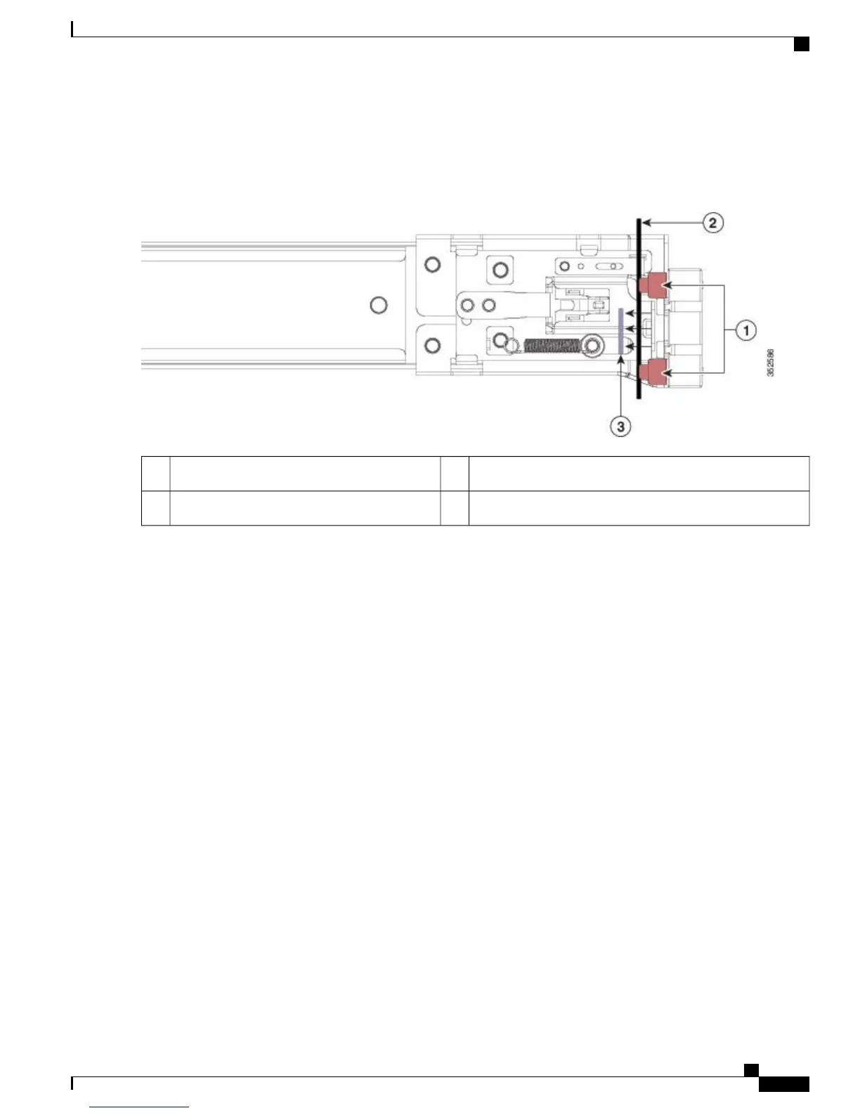
Figure 2: Front Securing Mechanism, Inside of Front End
Securing plate shown pulled back to Open position3Front-mounting pegs1
Rack post2
Step 3
Install the outer slide rails into the rack:
a) Align one slide-rail assembly front end with the front rack-post holes that you want to use.
The slide rail front-end wraps around the outside of the rack post and the mounting pegs enter the rack-post holes
from the outside-front (see Front Securing Mechanism, Inside of Front End).
The rack post must be between the mounting pegs and the open securing
plate.
Note
b) Push the mounting pegs into the rack-post holes from the outside-front.
c) Press the securing plate release button, marked PUSH. The spring-loaded securing plate closes to lock the pegs in
place.
d) Adjust the slide-rail length, and then push the rear mounting pegs into the corresponding rear rack-post holes. The
slide rail must be level front-to-rear.
The rear mounting pegs enter the rear rack-post holes from the inside of the rack post.
e) Attach the second slide-rail assembly to the opposite side of the rack. Ensure that the two slide-rail assemblies are
at the same height with each other and are level front-to-back.
f) Pull the inner slide rails on each assembly out toward the rack front until they hit the internal stops and lock in place.
Step 4
Insert the controller into the slide rails:
This controller can weigh up to 67 pounds (59 kilograms) when fully loaded with components. We recommend
that you use a minimum of two people or a mechanical lift when lifting the controller. Attempting this
procedure alone could result in personal injury or equipment damage.
Caution
a) Align the rear of the inner rails that are attached to the controller sides with the front ends of the empty slide rails on
the rack.
b) Push the inner rails into the slide rails on the rack until they stop at the internal stops.
Cisco 5520 Wireless Controller Installation Guide
5
Installing the Cisco 5520 Wireless Controller
Installing the Slide Rails

 Loading...