(11) Front service area for the line card replacement(4) Outside of the rack (no clearance required)
(12) Front chassis width(5) Rear chassis width
(13) Airflow direction(6) Clearance required for the fan tray handle at the
rear
(7) Rear service area for the fan tray and fabric card
replacement
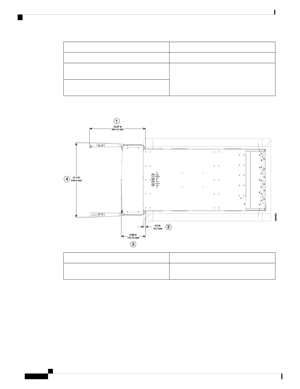
Following figure shows the clearances required for the cable management of Cisco 8800 Series Routers.
Figure 4: Clearances Required Around the Chassis Door
(3) Depth of cable management(1) Overall door width on side (in an open position)
(4) Overall door depth on front (in an open position)(2) Maximum vertical rack rail setback, when filters
are installed on the chassis
Prepare for Installation
10
Prepare for Installation
Clearance Requirements
 Loading...