2-12
Cisco 819 Integrated Services Router Hardware Installation Guide
OL-23125-02
Chapter 2 Installing the Router
Installing the Router
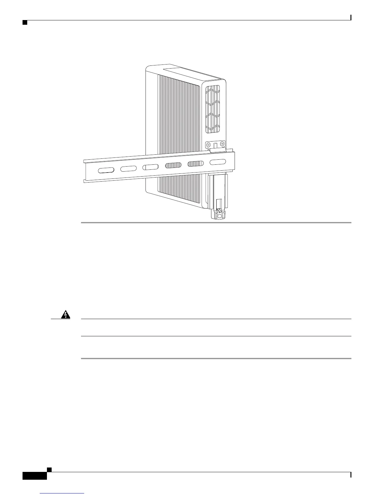
Figure 2-8 Cisco 819 ISR Installed with the DIN Rail
Installing the Router Ground Connection
The router must be connected to a reliable earth ground. Install the ground wire in accordance with local
electrical safety standards.
• For NEC-compliant grounding, use size 14 AWG (2 mm2) or larger copper wire and a ring terminal
with an inner diameter of 1/4 in. (5 to 7 mm).
• For EN/IEC 60950-compliant grounding, use size 18 AWG (1 mm2) or larger copper wire.
Warning
This equipment needs to be grounded. Use a green and yellow 12 to 14 AWG ground wire to connect
the host to earth ground during normal use.
Statement 242
To install the ground connection, follow these steps:
Step 1 Strip one end of the ground wire to the length required for the terminal.
Step 2 Crimp the ground wire to the ring terminal using the wire crimper.
Step 3 If you choose to install the power switch lock, perform Step 5 to Step 7.
If you choose not to install power switch lock, perform Step 4 and Step 6 to Step 7.
Step 4 Attach the ring terminal to the chassis. Use the single screw provided. Tighten the screws to a torque of
8 to 10 inch-pound (0.9 to 1.1 newton meter). (See
Figure 2-9.)