2-46
Cisco Integrated Services Router Hardware Installation Guide
Chapter 2 Installing the Router
Installing the Cisco 860, 880, 890 ISR
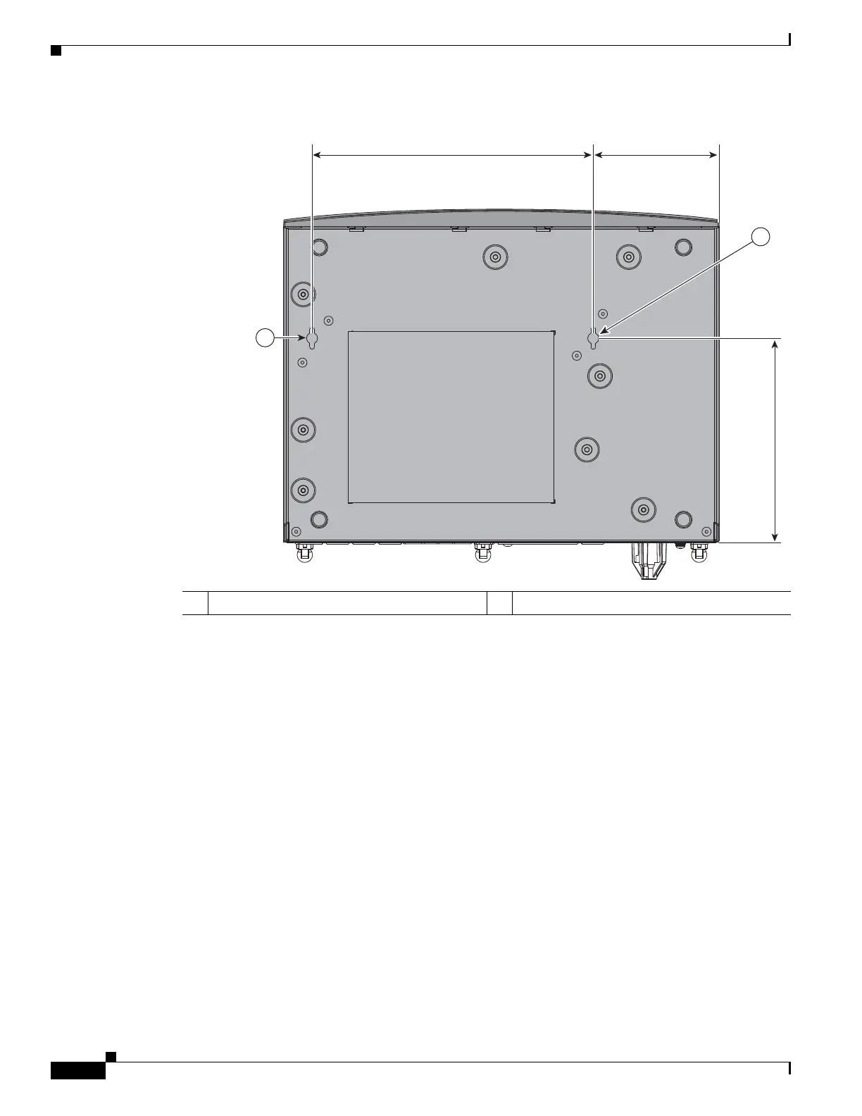
Figure 2-41 Wall-mount Holes on the Underside of the Router
Step 2
Insert the screws, with anchors, into the wall. Leave 1/8 inch (0.32 cm) between the screw head and the
wall. See Figure 2-42.
Step 3 Hang the router on the screw without forcibly pushing towards the wall side. The screw head may
damage the protection wall inside. Place the power adapter on a nearby horizontal surface. See
Figure 2-42.
1 Wall-mount holes
31987
1
5.961 in.
1