2-47
Cisco Integrated Services Router Hardware Installation Guide
Chapter 2 Installing the Router
Installing the Cisco 860, 880, 890 ISR
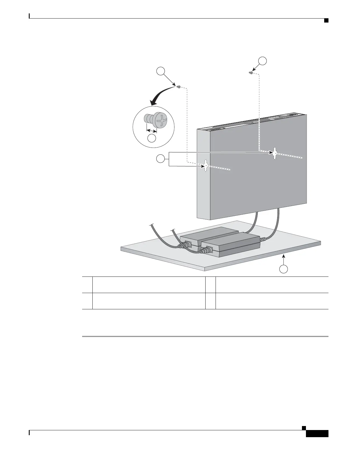
Figure 2-42 Router Mounted on the Wall
Step 4
Connect the chassis to a reliable earth ground. For the chassis ground connection procedures, see the
“Installing Cisco 890 Series in a Rack” section on page 2-56.
Installing the Router Ground Connection
The router must be connected to a reliable earth ground. Install the ground wire in accordance with local
electrical safety standards.
• For NEC-compliant grounding, use size 14 AWG (2 mm
2
) or larger copper wire and a ring terminal
with an inner diameter of 1/4 in. (5 to 7 mm).
• For EN/IEC 60950–compliant grounding, use size 18 AWG (1 mm
2
) or larger copper wire.
1 Two number-10 wood screws mounted on the
wall
3 Horizontal surface on which to place the
power adapter
2 Wall-mount holes 4 Distance between the screw head and the wall,
1/8 in. (0.32 cm)