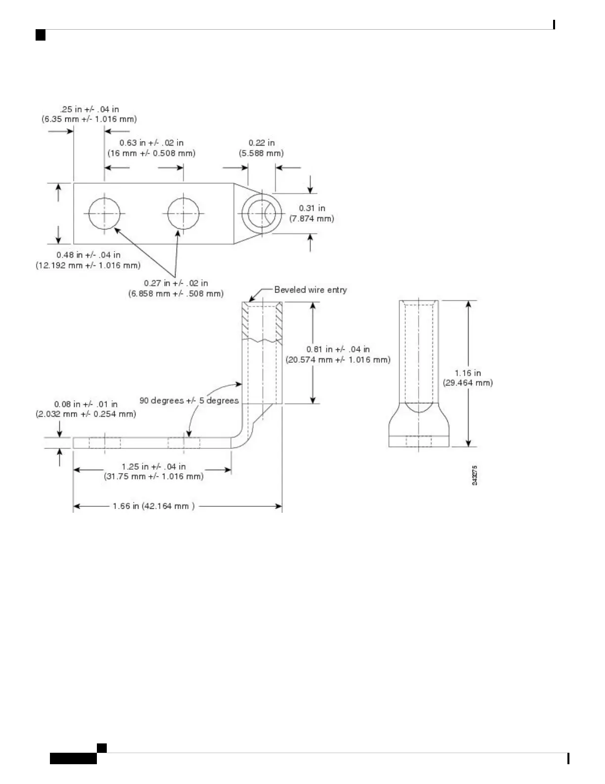
Figure 50: Typical DC Power Cable Lug
• Figure 51: Typical Source DC Power Cabling Scheme for a Single DC Power Module—Version 1 Power
System, on page 41 shows typical DC power source cable connections for a version 1 single DC power
module, in this case, a module installed in slot M2 of the power tray.
• Figure 52: Typical Source DC Power Cabling Scheme for a Single DC Power Module—Version 2 Power
System, on page 42 shows typical DC power source cable connections for a version 2 single DC power
module, in this case, a module installed in slot M3 of the power tray.
• Figure 53: Typical Plastic Safety Cover over the Power Tray Connection Terminals—Version 2 and
Version 3 Power System, on page 42 shows the plastic safety cover for the version 2 and version 3 DC
power tray connection terminals.
• Figure 54: Typical Source DC Power Cabling Scheme for a Single DC Power Module—Version 3 Power
System, on page 43 shows typical DC power source cable connections for a version 3 single DC power
module, in this case, a module installed in slot M3 of the power tray.
Cisco ASR 9000 Series Aggregation Services Router Hardware Installation Guide
40
Preparing for Installation
DC-Powered Router

 Loading...


