1000Base-T Signal100Base-TX SignalMGT LAN Port
Pin
BI_DC–Unused5
BI_DB–Receive–6
BI_DD+Unused7
BI_DD–Unused8
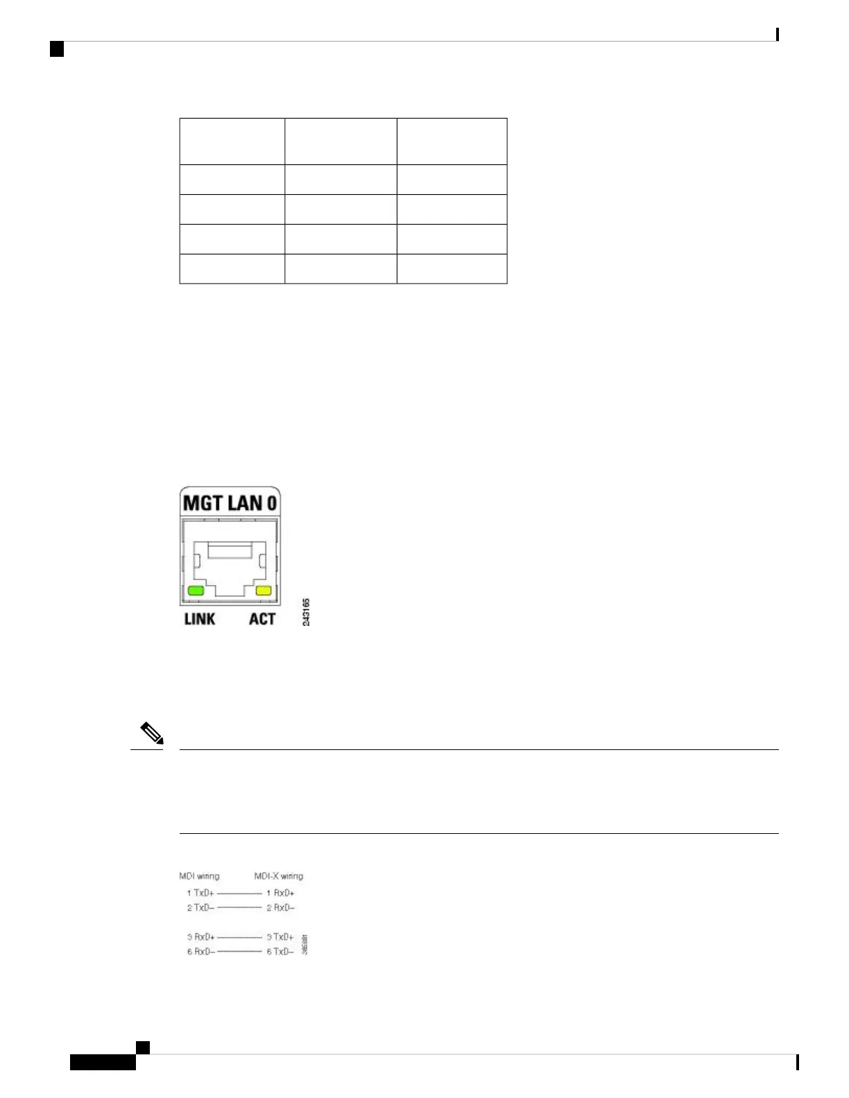
Management LAN Port LED Indicators
The Management LAN connectors have integral LED indicators. When lit, these LEDs indicate:
• Green (LINK)—Connection is alive.
• Amber (ACT)—Connection is active.
Figure 61: RSP/RP Management LAN Port LED Indicators
Management LAN RJ-45 Cabling
When connecting the RJ-45 port to a hub, repeater, or switch, use the straight-through cable pinout as shown
in the below figure.
To comply with the intrabuilding lightning surge requirements of Telecordia GR-1089-CORE, Issue II,
Revision 01, February 1999, you must use a shielded cable when connecting to the management LAN ports
on the RSP/RP card. The shielded cable is terminated by shielded connectors on both ends, with the cable
shield material tied to both connectors.
Note
Figure 62: Straight-Through Cable Pinout to a Hub, Repeater or Switch
Cisco ASR 9000 Series Aggregation Services Router Hardware Installation Guide
50
Preparing for Installation
Management LAN Port LED Indicators

 Loading...


