32 x T1/E1 Cable Connector
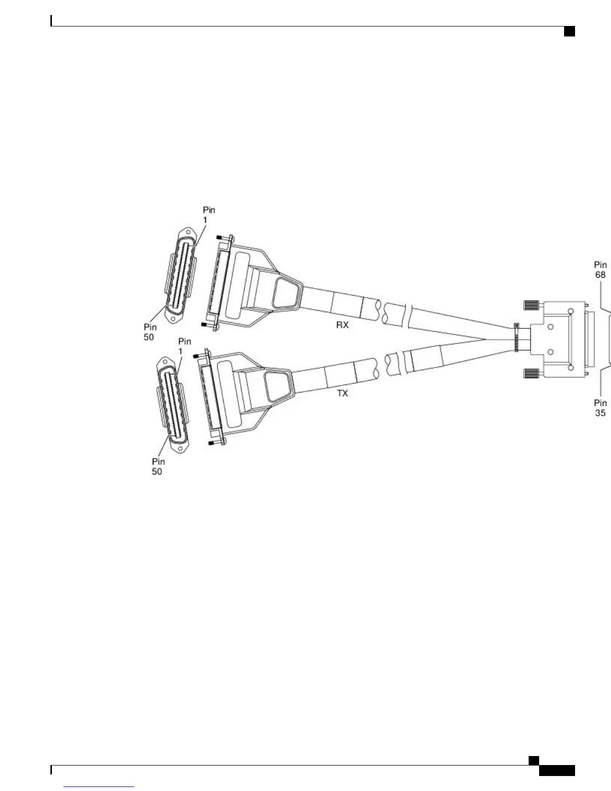
The 32 x T1/E1 interface module requires two patch cables (see Recommended Patch Panel). Each patch
cable (see the figure below ) has a 68-pin connectors that connects with each connector port on the front panel
of the 32 x T1/E1 interface module.
Use the thumbscrews on either side of the connectors to secure the cable to the interface.
Figure 37: 32 x T1/E1 Cable Connector
The other end of the cable has two 50-pin Telco connectors that attach to the rear of a 24-port RJ45 patch
panel. Both connectors are identical: one is for Transmit (TX) and the other is for Receive (RX).
Cisco ASR 903 and ASR 903U Aggregation Services Router Hardware Installation Guide
59
Installing the Cisco ASR 903 Router
Connecting T1/E1 cables

 Loading...


