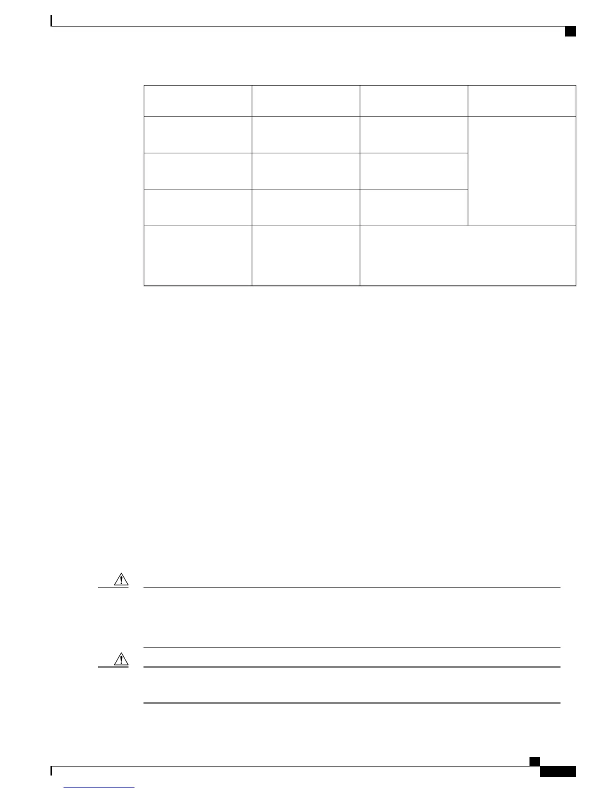
A900-RSP3C-400-SA900-RSP2A-64 and
A900-RSP2A-128
A900-RSP1
No supportNo support16 T1/E116 x T1/E1 Interface
Module
32 T1/E1No support32 x T1/E1 Interface
Module
8 T1/E1No support8 X T1/E1 Interface
Module
4-Port OC3/STM-1
(OC-3) or 1-Port
OC12/STM-4 (OC-12)
Interface Module
4-Port OC3/STM-1
(OC-3) or 1-Port
OC12/STM-4 (OC-12)
Interface Module
1
**Always refer to interface module compatibility matrix tables in the Data Sheet before you swap any IM.
Failure in executing the command may cause the interface to enter the Out of Service state. To recover from
out of service state, perform the following:
•
Insert the original IM and execute the hw-module subslot 0/bay default command. Swap the module.
For more information, see Cisco IOS Interface and Hardware Component Command Reference.
•
If the module does not come up, perform a reload of the router.
Installing the Power Supply
The Cisco ASR 903 Router provides the following power supply:
•
DC power
◦ 900 W DC power: –40VDC to –72VDC
The DC power supply provides option to connect with two different sources (dual feed); positive (+) and
negative (-) are marked on the PSU terminals.
Each power supply provides a dual primary input power connection.
The power supply must be wired before plugging the power supply in the chassis. Ensure the branch circuit
breaker is turned off. Only after installing the power supply in the chassis, should the branch circuit breaker
be turned on. The branch circuit breaker must be turned off before unplugging the power supply.Read the
installation instructions before connecting the system to the power source. Statement 10
Caution
Do not use interface module and power supply ejector handles to lift the chassis; using the handles to lift
the chassis can deform or damage the handles.
Caution
Cisco ASR 903 and ASR 903U Aggregation Services Router Hardware Installation Guide
31
Installing the Cisco ASR 903 Router
Installing the Power Supply

 Loading...


