Installing the DC Power Supply Module
Perform the following procedure to install the power supply module:
Step 1
Ensure that the system (earth) ground connection has been made. For ground connection installation instructions, see
Installing the Chassis Ground Connection.
Step 2
If necessary, remove the blank power supply filler plate from the chassis power supply bay opening by loosening the
captive installation screws.
Step 3
Verify that power to the DC circuit connected to the power supply you are installing is off. To ensure that power has
been removed from the DC circuits, locate the circuit breakers for the DC circuits, switch the circuit breakers to the OFF
position, and tape the circuit-breaker switches in the OFF position.
Step 4
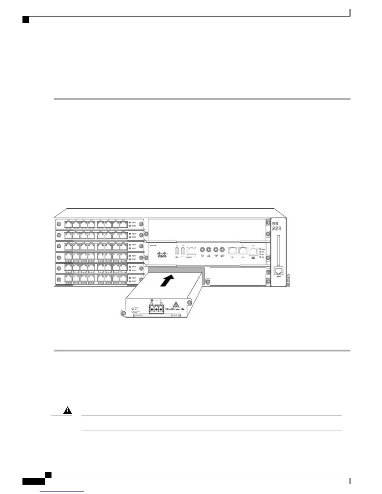
Grasp the power supply handle with one hand. Place your other hand underneath the power supply, as shown in the
figure below . Slide the power supply into the power supply bay. Make sure that the power supply is fully seated in the
bay.
Figure 26: Installing the DC Power Supply
Step 5
Tighten the captive installation screws of the power supply. The recommended maximum torque is 25 in.-lb (2.82 N-m).
If you are installing a redundant DC power supply, repeat these steps for the second power source.
Installing DC Power Supply Unit (A900-PWR900-D2)
The DC power supply accepts a dual-hole type lug. The lug must be a UL Listed, CSA certified and rated to
accept the 8 AWG cable. The lug is assembled on the unit with two nuts.
Before performing any of the following procedures, ensure that power is removed from the DC circuit.Warning
Cisco ASR 903 and ASR 903U Aggregation Services Router Hardware Installation Guide
34
Installing the Cisco ASR 903 Router
Installing the DC Power Supply

 Loading...


