FunctionColorLED
• Off: SIM0 is not installed
• Yellow: SIM0 is installed, but not active
• Green: SIM0 installed and active
• Green Blink: LTE data activity
SIM1 LED/ActivityGreen, YellowSIM1
• SIM1 LED status and WWAN activity
• Off: SIM1 is not installed
• Yellow: SIM1 is installed, but not active
• Green: SIM1 installed and active
• Green Blink: LTE data activity
GPS LEDGreen, YellowGPS
• Off: GPS is not configured
• Yellow: Software is defined
• Green: GPS is configured
• Green Blink: GPS is functional
Service Indication LED (Applicable for P-5GS6-GL)Green, Yellow, BlueService
• Yellow: 3G
• Green: 4G LTE
• Blue: 5G
RSSI LED (Applicable for P-LTE-XX, P-LTEA-XX,
P-LTEAP18-GL )
Green, YellowRSSI
• Green: 4G LTE
• Yellow: 3G
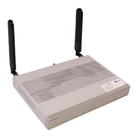
Attaching the Antennas
To attach the antenna in the Pluggable Interface Module, perform the below steps:
Hardware Installation Guide for the Cisco 1000 Series Integrated Services Router
72
Install and Upgrade Internal Modules and Field Replaceable Units
Attaching the Antennas




 To Next Page