EasyManuals Logo

Cisco Catalyst 2950 Getting Started Guide

Cisco Catalyst 2950
28 pages
To Next Page IconTo Next Page
To Previous Page IconTo Previous Page
Page #17 background imageLoading...
Page #17 background image
17
Wiring the DC Input Power Source
Follow these steps:
Step 3
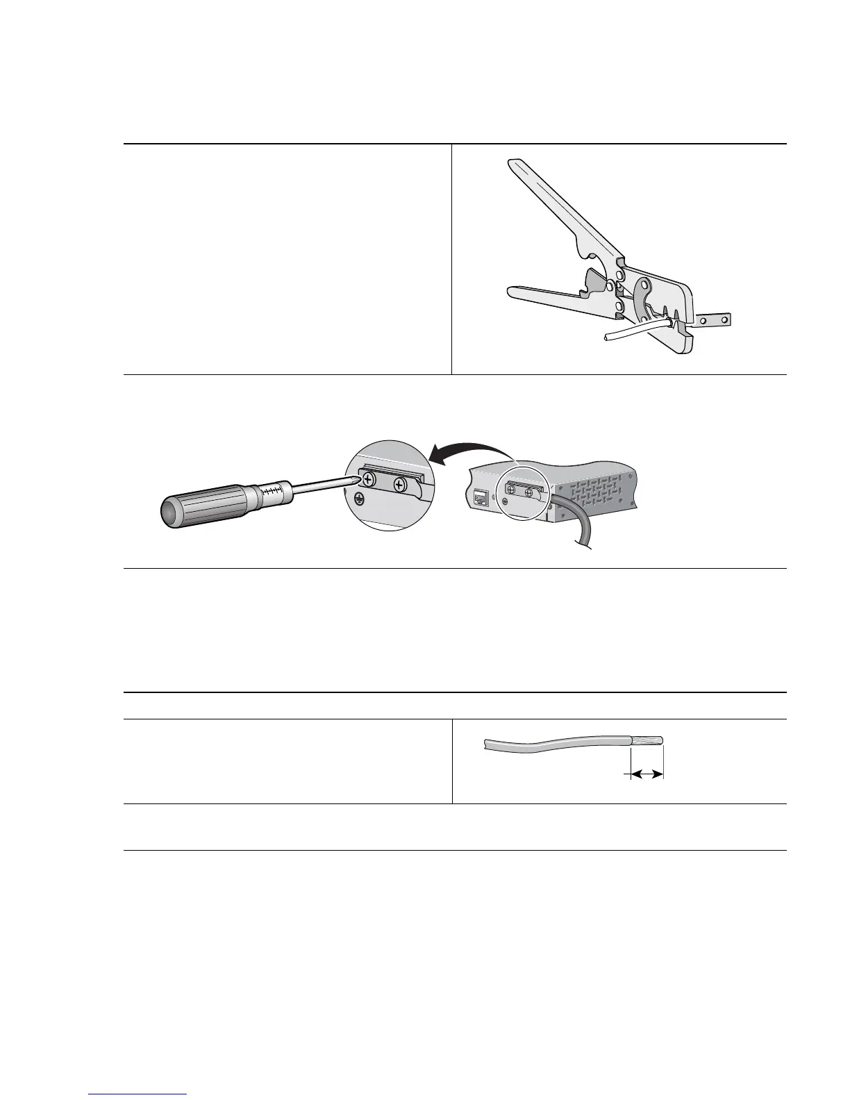
Slide the exposed area of the 6-gauge wire
into the ground lug, and use the crimping
tool to crimp the lug to the wire.
Step 4
Using the ratcheting screwdriver, torque the ground lug screws to 15 lbf-in. (240
ounce-force inches [ozf-in.]) to attach the ground lug to the switch.
Step 1
On the terminal block connector, identify the positive and negative feed positions.
Step 2
Strip each of the four wires coming from the
DC power source to 0.27 inch (6.6 mm)
± 0.02 inch (0.5 mm). Do not strip more
than the recommended amount of wire.
Step 3
Insert the four exposed wires from the DC-input power source into the terminal block plug,
matching positive to positive and negative to negative for both the A and the B feed wires.
CO
NSOLE
0.27 inch (6.6 mm)

Other manuals for Cisco Catalyst 2950

Questions and Answers:

Question and Answer IconNeed help?

Do you have a question about the Cisco Catalyst 2950 and is the answer not in the manual?

Cisco Catalyst 2950 Specifications

General IconGeneral
Forwarding Bandwidth8.8 Gbps
Switching Capacity13.6 Gbps
Forwarding Rate6.6 Mpps
Weight3.6 kg
RAM16 MB
Flash Memory8 MB
Operating Humidity10% to 85% non-condensing
Uplink Ports2 x 10/100/1000Base-T
Dimensions4.4 cm x 44.5 cm x 24.2 cm
Remote Management ProtocolSNMP, Telnet, HTTP
FeaturesQuality of Service (QoS), VLAN support
Compliant StandardsIEEE 802.3, IEEE 802.3u, IEEE 802.1D, IEEE 802.1Q, IEEE 802.1p
Status Indicatorssystem
Operating Temperature0 to 45°C
Ports24 x 10/100 Ethernet ports
MAC Address Table Size8, 192 entries
Power SupplyInternal 100-240V AC, 50-60Hz

Related product manuals