18
Caution You must connect the Catalyst 2950G-24-EI-DC or Catalyst 2950ST-24 LRE 997 switch
only to a DC-input power source that has an input supply voltage from –36 to –72 VDC.
If the supply voltage is not in this range, the switch might not operate properly or might
be damaged.
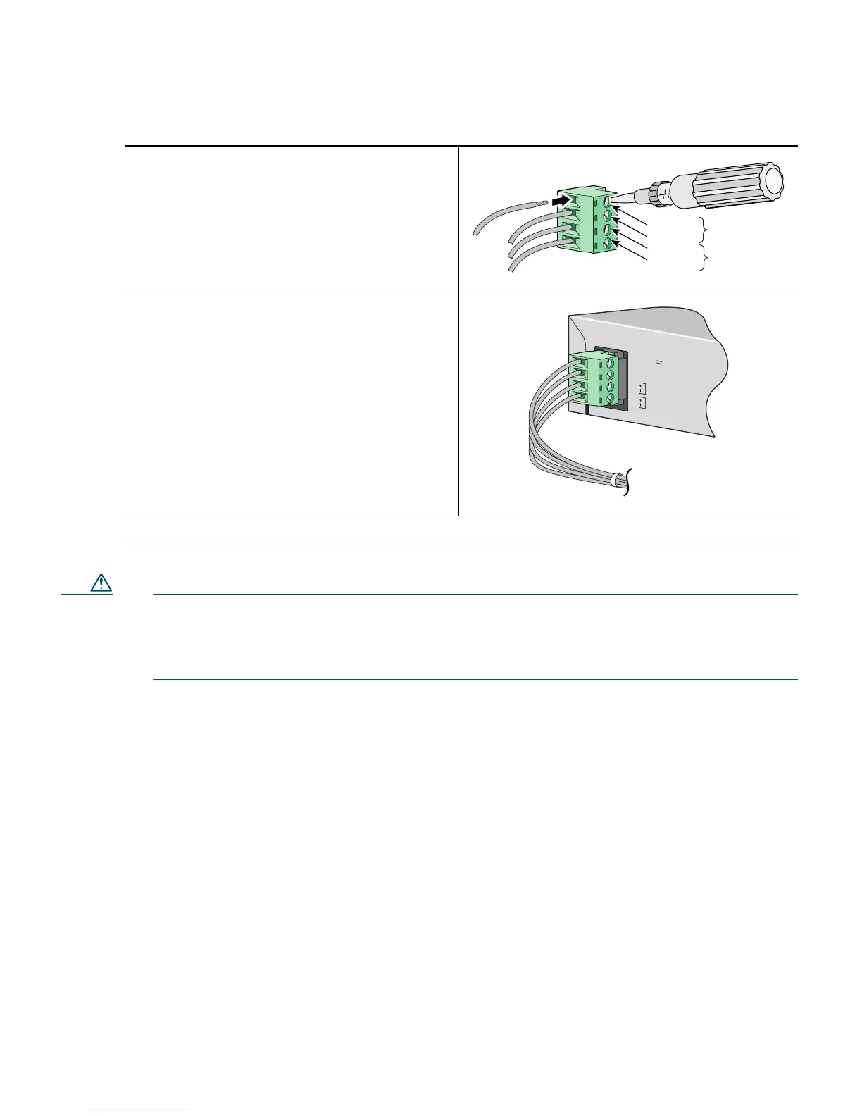
Step 4
Using the ratcheting torque screwdriver,
torque each terminal block captive screw
(above the installed wire leads) to 4.5 lbf-in.
(72 ozf-in.).
Step 5
Insert the terminal block plug in the terminal
block header on the rear panel of the
Catalyst 2950G-24-EI-DC switch or on the
front panel of the Catalyst 2950ST-24
LRE 997 switch.
Step 6
Move the circuit-breaker handle for the DC power source to the on position.
Return
Negative
Return
Negative
Feed A
Feed B
36 - 72V
1 - 0.5A
A
B