50
Installing and Connecting the Router
Auxiliary Port, Console Port, and Adapter Pinouts for the Cisco CGR 2010 Router
Figure 21 RJ-45 to DB-25 Adapter (Terminal)
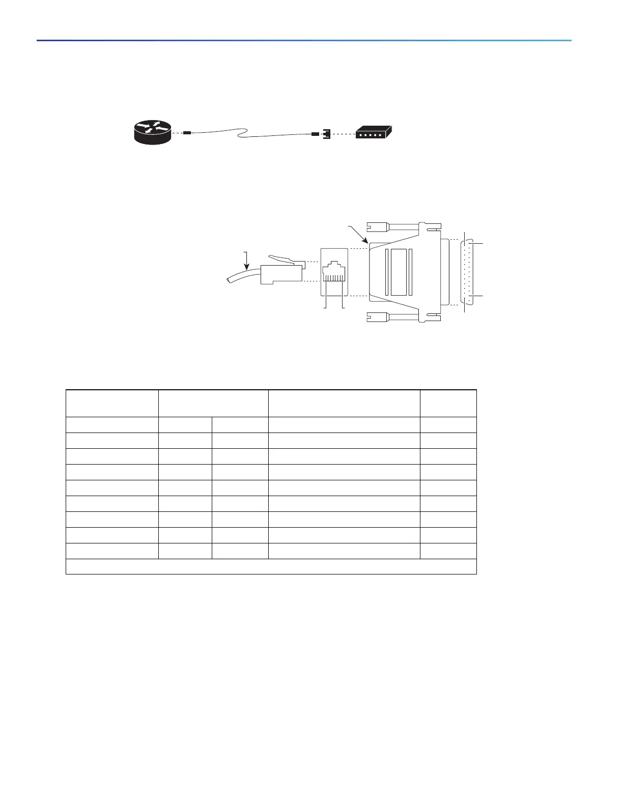
Figure 22 RJ-45 to DB-25 Male Adapter
Table 9 on page 50 provides the pinout description for the modem connection:
Alternative Terminal and Modem Connections
Table 10 on page 51 describes the alternative terminal and modem connections:
Table 9 Pinout Descriptions for the Modem Connection
Auxiliary Port (DTE) RJ-45 to RJ-45
Rollover Cable
RJ-45 to DB-25 Modem Adapter Modem
Signal RJ-45 Pin RJ-45 Pin DB-25 Pin Signal
RTS 1
1
85 CTS
DTR 2 7 6 DSR
TxD 3 6 3 RxD
GND 4 5 7 GND
GND 5 4 7 GND
RxD 6 3 2 TxD
DSR 7 2 20 DTR
CTS 8 1 4 RTS
1
Pin 1 is connected internally to Pin 8.
Modem
RJ-45-to-DB-25
adapter
(labeled Modem)
RJ-45-to-RJ45
roll-over cable
Router
239794
MODEM
CAB-5MODCM
RJ-45 cable
RJ-45-to-DB-25 male adapter
239783
8
1
1
25
13
14