E-16
Cisco Physical Security Multiservices Platform Series User Guide
OL-21838-03
Appendix E 16 x D1 and 8 x D1 Video Capture Cards
Configuration Instructions for Cisco Video Surveillance
Multiple Camera Configuration
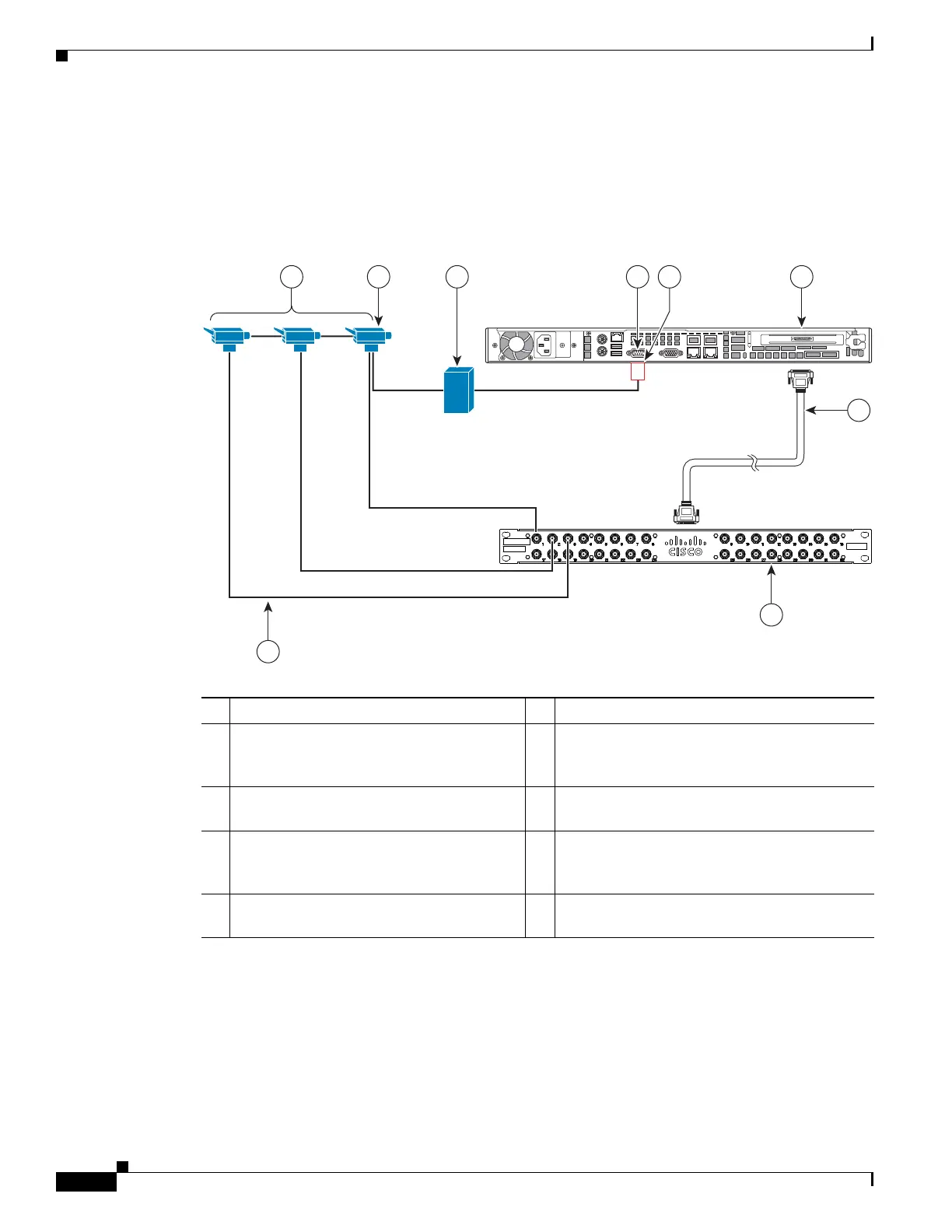
To connect multiple cameras, you must use a Cisco data converter to convert the RS-232 serial signals
to RS-485/RS-422. Multiple cameras are only supported with RS-485/RS-422 serial connections.
Figure E-12 summarizes the cable connections in a multi-camera configuration.
Figure E-12 Multiple Analog PTZ Camera: Serial and BNC Cable Connections
1 First analog PTZ camera in the daisy-chain. 6 Multi-channel video cable.
2 Data converter to convert RS-232 serial
signals to RS-485/RS-422 (see
Figure E-13).
7 BNC breakout panel.
3 RS-232 serial port on the 1-RU or 2-RU
Multiservices Platform Series.
8 BNC video cables connected between each
camera and the BNC breakout panel.
4 Serial cable adapter used to connect
individual RS-232 wires from the camera
(see
Figure E-13).
9 Additional analog cameras connected with
serial cables in a daisy-chain configuration.
5 16 x D1 and 8 x D1 video capture cards
installed in a Multiservices Platform Series.
1
20
279924
Serial
cable
Serial
cable
RS-232 Serial cable
RS-485/
RS-422
Serial
cable
BNC video cable
BNC video cable
BNC video cable
Data
Converter
1 5
7
8
2 3 4
6
9
 Loading...