SSD2 Alert Status
• Off—SSD has normal activity.
• Amber—SSD failure.
12SSD1 Alert Status
• Off—SSD has normal activity.
• Amber—SSD failure.
11
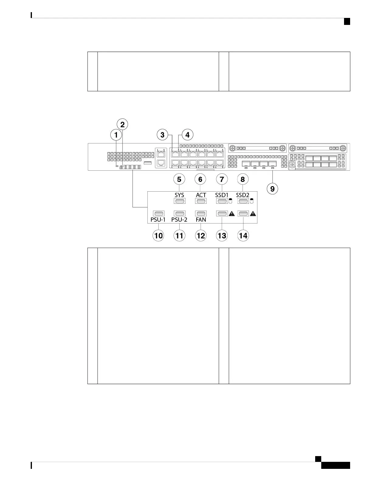
The following figure shows the Firepower 2130 and 2140 front panel LEDs.
Figure 12: Firepower 2130 and 2140 Front Panel LEDs
Locator
• Off—Locate is off.
• Blue—Locate is on.
The Locator LED helps you locate a
unit that needs physical service
attention. This feature is activated in
the software.
Note
2Power
• Off—Input power is not detected. Standby
power is off.
• Green, flashing—The system has detected
a power switch toggle event, and initiated
the shutdown sequence. If the power switch
is in the OFF position, the system powers
off after shutdown is completed. Do not
remove the AC or DC power source while
this LED is blinking so that the system has
time to perform a graceful shutdown.
• Amber—The system is powering up (before
the BIOS boots). This takes one to five
seconds at most.
• Green—The system is fully powered up.
1
Cisco Firepower 2100 Series Hardware Installation Guide
15
Overview
Front Panel LEDs
 Loading...


