EasyManuals Logo

Cisco Firepower 2140 Hardware Installation Guide

Cisco Firepower 2140
84 pages
To Next Page IconTo Next Page
To Previous Page IconTo Previous Page
Page #62 background imageLoading...
Page #62 background image
Statement 1025—Use Copper Conductors Only
Use copper conductors only.
Warning
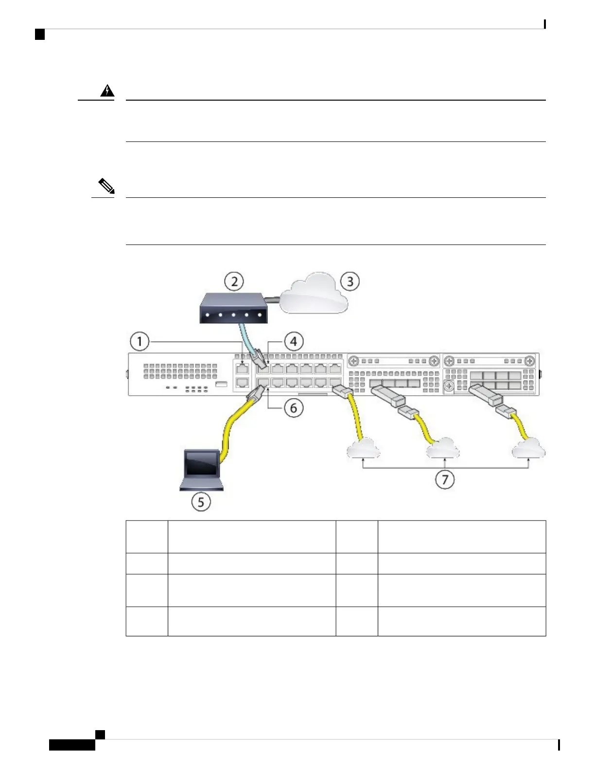
After rack-mounting and grounding the Firepower 2100, follow these steps to connect cables, turn on power,
and verify connectivity.
The following figure shows the default configuration using a management computer connected to the inside
network. Your deployment may vary depending on your basic logical network connectivity, ports, addressing,
and configuration requirements.
Note
Figure 43: Connect Cables to Firepower 2100 Interfaces
WAN modem2(Alternative) Management 1/1
192.168.45.45
1
Ethernet 1/1 (outside, DHCP from modem)4Internet3
Ethernet 1/2 (inside 192.168.1.1)6Management computer (DHCP from inside
192.168.1.x)
5
Other data networks (SFP/SFP+
transceivers)
7
Cisco Firepower 2100 Series Hardware Installation Guide
58
Mount and Connect
Connect Cables, Turn on Power, and Verify Connectivity for Cisco Firepower Threat Defense

Other manuals for Cisco Firepower 2140

Questions and Answers:

Question and Answer IconNeed help?

Do you have a question about the Cisco Firepower 2140 and is the answer not in the manual?

Cisco Firepower 2140 Specifications

General IconGeneral
ModelCisco Firepower 2140
CategoryFirewall
Firewall Throughput20 Gbps
Power SupplyDual, Hot-swappable
Firewall Throughput (Maximum)20 Gbps
Firewall Throughput (Application Visibility and Control AVC)10 Gbps
Form Factor1 RU
Memory32 GB
Operating SystemCisco Firepower Threat Defense (FTD)
Maximum Concurrent Sessions4, 000, 000
Network Interfaces8 x 1G/10G SFP+
Concurrent Sessions4, 000, 000
Interfaces8 x 1G/10G SFP+
Throughput20 Gbps

Related product manuals